AUTOMATIC TRANSMISSION SYSTEM
-
CONSTRUCTION
-
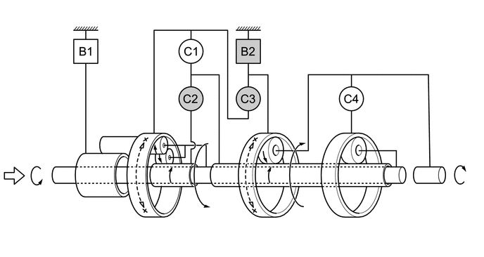
The gear train is composed of 2 sets of multi-plate type brakes, 4 sets of multi-plate type clutches and 3 sets of planetary gear units.
-
The tooth number, position and contact area of the gears are optimized to reduce the amount of gear noise.
-
Optimally-designed groove shapes are used in the friction material of the clutch and brake portions to reduce losses due to drag. As a result, this helps improve fuel economy performance.
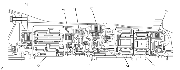
*1 No. 1 Brake (B1) *2 Front Planetary Gear Unit *3 No. 3 Clutch (C3) *4 Middle Planetary Gear Unit *5 Rear Planetary Gear Unit *6 No. 4 Clutch (C4) *7 No. 2 Brake (B2) *8 No. 1 Clutch (C1) *9 No. 2 Clutch (C2) - - 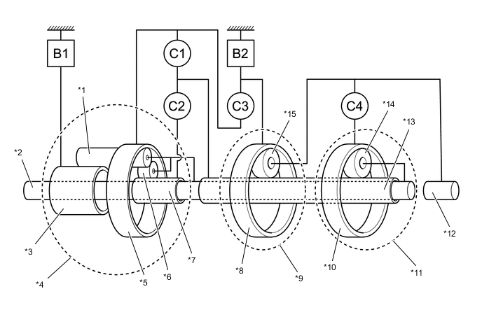
*1 Front Planetary Long Pinion Gear *2 Input Shaft *3 Front Planetary Large Sun Gear *4 Front Planetary Gear Unit *5 Front Planetary Ring Gear *6 Front Planetary Short Pinion Gear *7 Front Planetary Small Sun Gear *8 Middle Planetary Ring Gear *9 Middle Planetary Gear Unit *10 Rear Planetary Ring Gear *11 Rear Planetary Gear Unit *12 Output Shaft *13 Middle/Rear Planetary Sun Gear *14 Rear Planetary Pinion Gear *15 Middle Planetary Pinion Gear - - C1 No. 1 Clutch C2 No. 2 Clutch C3 No. 3 Clutch C4 No. 4 Clutch B1 No. 1 Brake B2 No. 2 Brake
Component Operation No. 1 Clutch (C1)
-
Connects the front planetary ring gear and middle/rear planetary sun gear.
-
Connects the middle/rear planetary sun gear and middle planetary ring gear when the No. 3 clutch is in operation.
No. 2 Clutch (C2)
-
Connects the front planetary small sun gear and rear planetary sun gear.
-
Connects the front planetary small sun gear and front planetary ring gear when the No. 1 clutch is in operation.
No. 3 Clutch (C3)
-
Connects the front planetary ring gear and middle planetary ring gear.
-
Connects the middle/rear planetary sun gear and middle planetary ring gear when the No. 1 clutch is in operation.
No. 4 Clutch (C4) Connects the middle planetary carrier and rear planetary ring gear. No. 1 Brake (B1) Locks the rotation of the front planetary large sun gear. No. 2 Brake (B2)
-
Locks the rotation of the middle planetary ring gear.
-
Locks the rotation of the front planetary ring gear when the No. 3 clutch is in operation.
-
-
OPERATION
-
Transmission Power Flow
Figure 1. Operating Condition of Shift Solenoid Valves
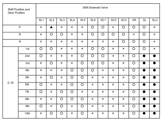
○: On
X: Off
▲: Control
●: When lockup is operating, SL is off and SLU is on. When lockup is not operating, SL is on and SLU is off.
Figure 2. Operating Condition of Clutches and Brakes
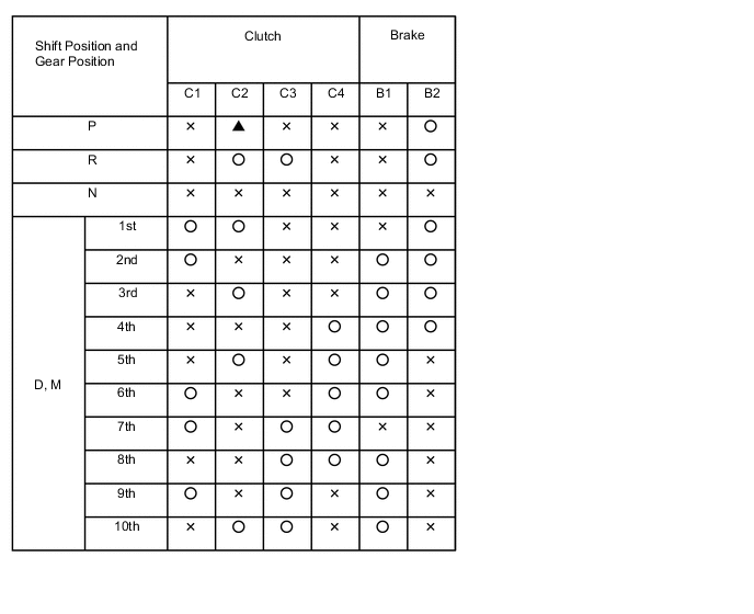
○: Operates
X: Does not Operate
▲: Control
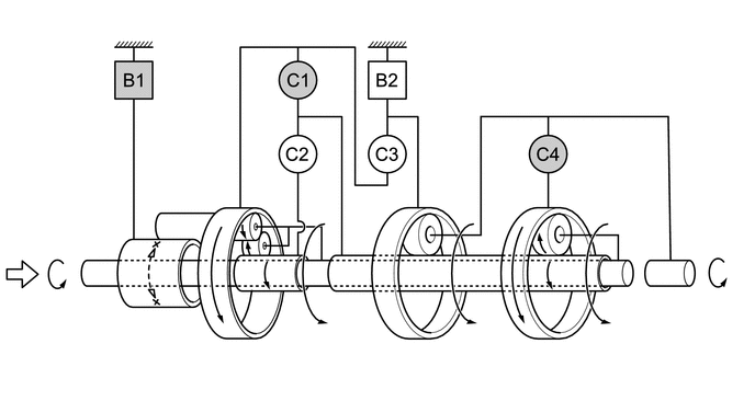
Figure 3. 1st
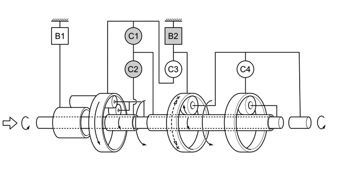

Input 
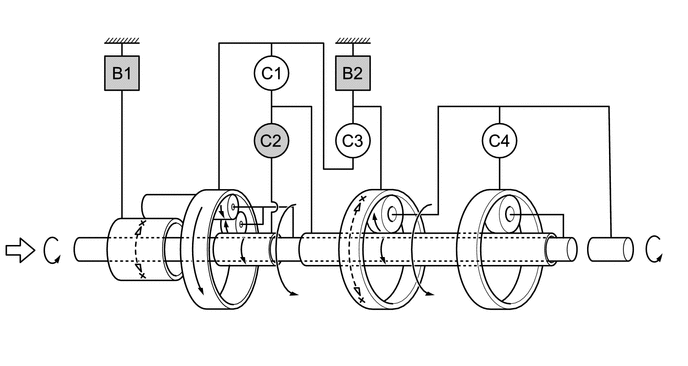
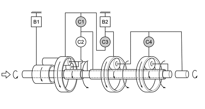
Operation Figure 4. 2nd

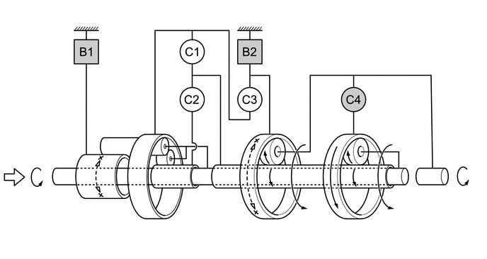
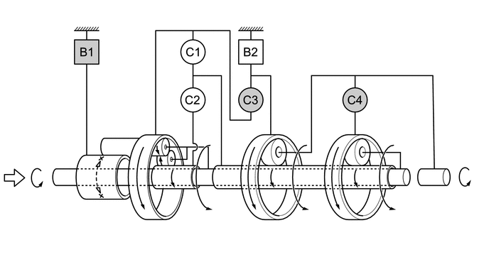
Input Operation Figure 5. 3rd
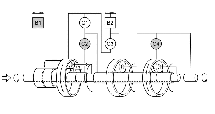
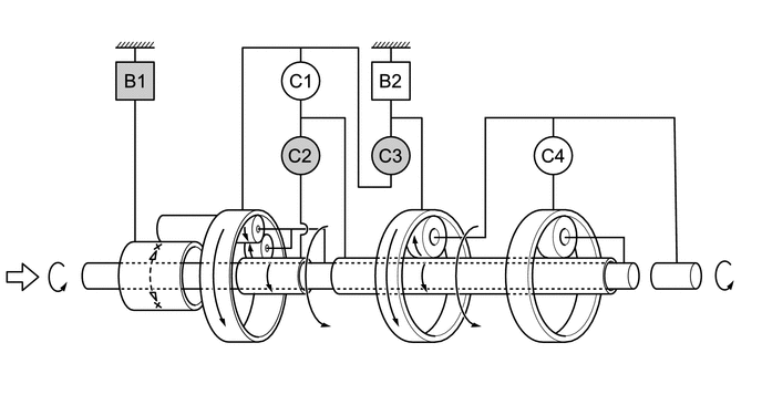
Input Operation Figure 6. 4th
Input Operation Figure 7. 5th
Input Operation Figure 8. 6th
Input Operation Figure 9. 7th
Input Operation Figure 10. 8th
Input Operation Figure 11. 9th

Input Operation Figure 12. 10th
Input Operation Figure 13. Reverse
Input Operation
-