AUTOMATIC TRANSMISSION SYSTEM
-
FUNCTION OF MAIN COMPONENTS
Component Function Solenoid Valve SL1 Controls the No. 1 clutch (C1) pressure. Solenoid Valve SL2 Controls the No. 2 clutch (C2) pressure. Solenoid Valve SL3 Controls the No. 3 clutch (C3) pressure. Solenoid Valve SL4 Controls the No. 4 clutch (C4) pressure. Solenoid Valve SL5 Controls the No. 1 brake (B1) pressure. Solenoid Valve SL6 Controls the No. 2 brake (B2) pressure. Solenoid Valve SC1 Switches the No. 2 B2 apply control valve. Solenoid Valve SC2 Switches the No. 1 D-N-R shift valve. Solenoid Valve SC3 Switches the No. 2 D-N-R shift valve. Solenoid Valve SLT Controls the line pressure. Solenoid Valve SLU Controls the lock-up clutch pressure. Solenoid Valve SL Switches the lock-up relay valve. Solenoid Valve SR
-
Switches the sequence valve.
-
Switches the No. 1 B2 apply control valve.
Transmission Revolution Sensor (NT) Detects the input speed of the transmission. Transmission Revolution Sensor (SP2) Detects the output speed of the transmission. ATF Temperature Sensor Detects the ATF temperature. Yawrate Sensor
-
Detects the vehicle's longitudinal and lateral acceleration.
-
Detects the vehicle's yaw rate.
Accelerator Pedal Sensor Assembly Detects the accelerator pedal opening angle. Stop Light Switch Assembly Detects the brake pedal depressing signal. Paddle Shift Switch (Transmission Shift Switch Assembly) Detects the shift-up and shift-down operations performed by the driver. Satellite Switch Set Drive Mode Select Switches the driving mode. Satellite Switch Set SNOW Switch*1 Switches to the SNOW mode. Transmission Floor Shift Assembly Shift Lever Position Sensor Detects the shift position (Home, R, N, D or M) and transmits the shift position signal to the shift control ECU. Combination Meter Assembly MIL Illuminates or blinks to inform the driver when the ECM detects a malfunction. Drive Mode Indicator Displays the drive mode. Shift Position Indicator
-
Indicates the shift position (P, R, N, D or M).
-
Indicates the gear position.
-
Indicates the shift range.
Master Warning Light Warns the driver by lighting up when a message is shown on the multi-information display. Multi-information Display
-
Displays the warning message when the ECM detects a malfunction.
-
Warns the driver by displaying a message when the ATF is at a high temperature.
Buzzer
-
Sounds when a shift-down operation is rejected.
-
Sounds together with a message display on the multi-information display during a system malfunction.
ECM
-
Controls engine output and each shift solenoid valve in response to a signal from each sensor and switch.
-
Makes a diagnosis and memorizes the failed section when the ECM detects a malfunction.
Brake Actuator Assembly
-
Skid Control ECU
Sends information about the operation conditions of the brake control system to the ECM. Driving Support ECU Assembly*2 Sends information about the operation conditions of the dynamic radar cruise control system to the ECM. Shift Control ECU
-
Performs shift control for each shift position based on signals from the shift lever position sensor, P position switch and various ECUs and sends control signals to the ECM.
-
Operates the parking lock motor inside the shift control actuator assembly based on P position switch operation signals and the vehicle condition.
*1: Except models for G.C.C. countries
*2: Models with dynamic radar cruise control system
-
-
SYSTEM CONTROL
-
The AGA0E 10-speed automatic transmission uses the following controls.
Control Function Shift Timing Control Performs shifting control according to the shift position, vehicle speed, accelerator opening angle and driving conditions. Driving Response and Acceleration Management System (DRAMS) Integrates controls for the engine, transmission and related systems, which form the base for the vehicle's motive force, to improve maneuverability and comfort and achieve a superior driving feel. Direct Connected Downshift Control Uses a control to perform shifting in order, high-precision oil pressure control and highly responsive shift solenoid valves to achieve linear engine speed changes during downshifting and smooth motive force changes that are linked with the engine speed. D-range Paddle Active Control Enables paddle shift switch (transmission shift switch) operations in the D range to fix the range. M Mode Control Uses gear hold control, high response upshift control, blipping downshift control and complete lock-up control to improve the response and feel of manual operations, providing driving pleasure during sporty driving. Coast Downshift Control Achieves low fuel consumption by performing fuel cut control as long as possible during deceleration. Lock-up Timing Control Performs lock-up timing control according to the shift position, vehicle speed, accelerator opening angle and driving conditions. Flex Lock-up Clutch Control Generates stable lock-up clutch sliding to make lock-up operation possible in a wider range, achieving superior fuel efficiency characteristics. Drive Mode Select Makes it possible to select the driving mode by performing switch operations. Artificial Intelligence-shift Control (AI-shift Control) Automatically switches the shift pattern according to road conditions and the driver's intentions. Line Pressure Control Controls the line hydraulic pressure to the optimal pressure based on engine torque information. Line Pressure Optimal Control Uses the shift solenoid valves to precisely control the clutch hydraulic pressure according to the engine output and driving conditions. Clutch to Clutch Pressure Control Uses the shift solenoid valves to directly control the clutch and brake, making it possible to achieve a compact transmission and perform high-precision shifting control. Differential Protection Control Prohibits gear shifting to protect the differential when a large speed difference occurs between the left and right driving wheels (such as when the left and right driving wheels are traveling on surfaces with different friction coefficients). ATF High Temperature Control Switches from the normal shift pattern to the high oil temperature shift pattern to prevent the oil temperature from increasing further when the oil temperature is high.
-
Driving Response and Acceleration Management System (DRAMS)
-
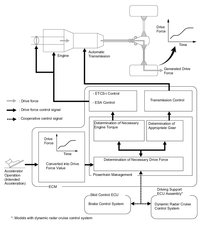
A system for integrally controlling the motive force, which has been named the Driving Response and Acceleration Management System (DRAMS), is used. This system achieves a more optimal driving feel (including the vehicle behavior) by considering driver requests and the surrounding environment. It integrates controls for the engine, transmission and related systems, which form the base for the vehicle's motive force, to improve maneuverability and comfort.
-
The Driving Response and Acceleration Management System (DRAMS), converts accelerator pedal operations into the motive force requested by the driver, judges the engine torque and gear position required to achieve that requested motive force, and integrally controls the engine and transmission. As a result, the motive force desired by the driver is generated, achieving a superior driving feel. In addition, DRAMS integrative control is performed according to the motive force requested by VDIM and the cruise control system, improving the control performance of the systems.
-
High speed responsiveness according to the driver's intentions and a superior driving feeling are achieved even during a shift transition, start-off and deceleration.
-
Throttle Control at Launch
-
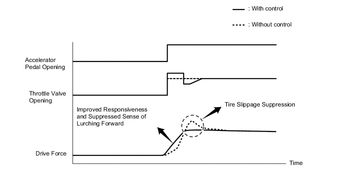
Electronic Throttle Control System-intelligent (ETCS-i) and cooperative control are used to optimally control the engine torque, improving the feeling of acceleration when initially depressing the accelerator pedal. As a result, responsive acceleration is achieved and high-quality start-off performance is made possible, suppressing feelings of lurching.
-
Sport mode*1 or Sport S/S+ mode*2 emphasize the responsiveness of control performed during reacceleration to achieve the motive force requested by the driver, improving driveability.
*1: Models without AVS
*2: Models with AVS
-
-
Control Helping Improve Fuel Efficiency and Quietness
-
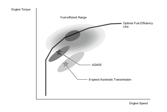
When the accelerator pedal opening angle is low, control is performed to reduce the engine speed as much as possible and use the highly efficient range of the engine, helping improve fuel efficiency and quietness.
-
-
Drive Force Control Achieving Fuel Efficiency and Driveability
-
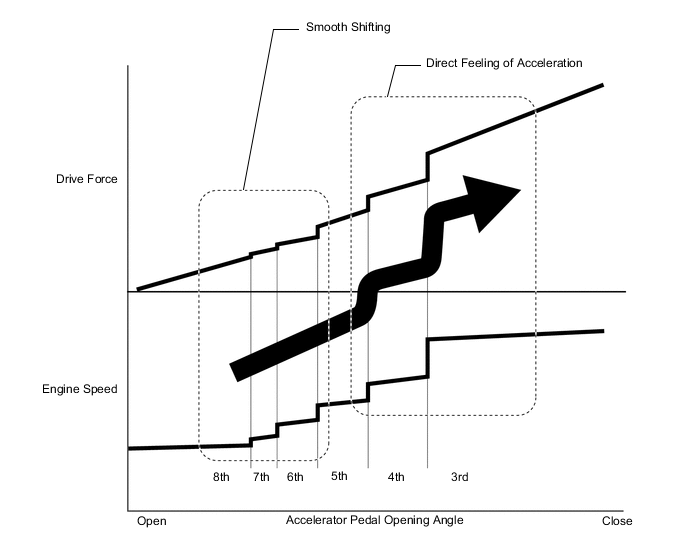
Motive force control provides the drive force of each shift position with a certain degree of freedom, achieving the motive force requested by the driver. In ranges where the accelerator pedal is only lightly depressed, the highly efficient range of the engine is proactively used to improve fuel efficiency performance. In addition, the difference in drive force between each gear position is minimized, achieving smooth shifting. On the other hand, in ranges where the accelerator pedal is heavily depressed, the motive force is generated according to changes in the engine speed, achieving a direct feeling of acceleration. As a result, fuel efficiency and driveability are achieved.
-
-
-
Direct Connected Downshift Control
-
Direct connected downshift control is used to achieve linear engine speed changes during downshifting and smooth drive force changes that are linked with the engine speed.
-
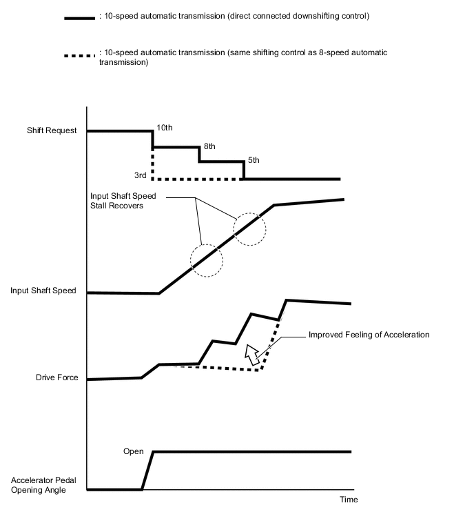
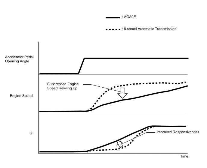
A 10-speed automatic transmission has wider gear ratios than an 8-speed automatic transmission. Therefore, the amount of time it takes until acceleration is felt when shifting at the same speed as an 8-speed automatic transmission is greater, such as when depressing the accelerator pedal to downshift from a higher gear to a lower gear. Also, in order to reduce the amount of time it takes until acceleration is felt, control is used to perform shifting in order. However, during that time, each time shifting is performed, the input shaft speed stalls and the amount of time required to reach the target gear increases. Therefore, high-precision oil pressure control and highly responsive shift solenoid valves are used to prevent stalls from occurring and directly connect each gear change, achieving smooth and highly responsive downshifting.
Figure 1. Comparison of Same Shifting Speed
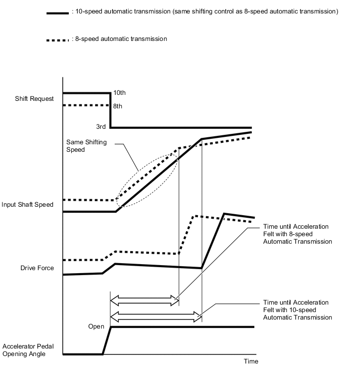
Figure 2. Comparison when Shifting in Order
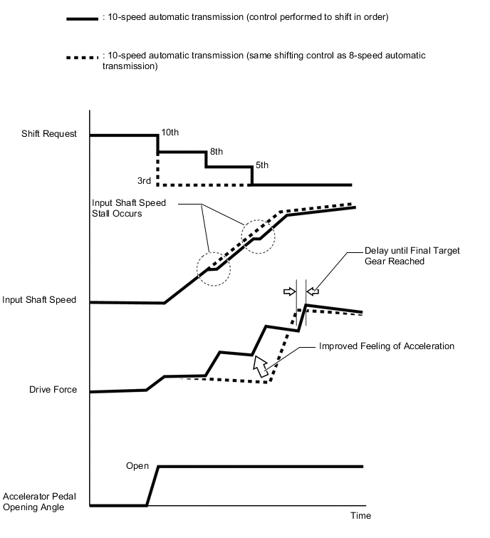
Figure 3. Comparison during Direct Connected Downshifting Control
-
-
D-range Paddle Active Control
-
When a paddle shift switch (transmission shift switch) operation is performed while the shift position is in D, D-range paddle active control operates to fix the range. As a result, it is possible for the driver to perform upshift and downshift operations when the shift position is D without removing their hands from the steering wheel.
-
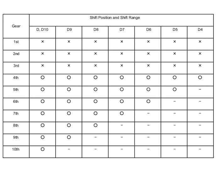
During D-range paddle active control, gear shifting is performed automatically according to the vehicle speed and driving conditions in the usable gear position range of the selected shift range.
-
The initial range when D-range paddle active control starts is determined according to the last gear position and speed before paddle shift switch (transmission shift switch) operation.
Initial Range when Control Starts Gear Position before Shift Paddle Operation Initial Range after Shift Paddle "-" (Downshift) Operation Initial Range after Shift Paddle "+" (Upshift) Operation 1st D1 D2 2nd D1 D3 3rd D2 D4 4th D3 D5 5th D4 D6 6th D4, D5* D7 7th D5, D6* D8 8th D5, D6, D7* D9 9th D6, D7, D8* D10 10th D7, D8, D9* D10 *: Select the optimum range according to the speed
-
Normal driving automatically resumes (automatic shift control) in the following conditions:
Normal Driving (Automatic Shift Control) Recovery Conditions
-
The vehicle has stopped.
-
The driver continues to push the paddle shift switch (transmission shift switch assembly) in the "+" direction longer than 1 second.
-
The driver moves the shift lever to D.
-
The driver depresses the accelerator pedal for more than a predetermined amount time.
-
-
-
M Mode Control
-
When the shift position is M, paddle shift switch (transmission shift switch) operations can be performed to enable a drive with selected gear positions.
-
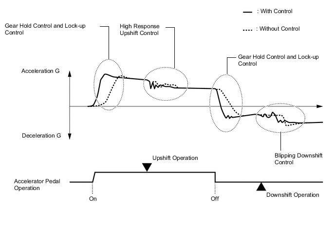
M mode control is a control specification designed so that drivers can enjoy sporty driving. It emphasizes the direct feel of accelerator pedal operation and the responsiveness and feel of manual shifting.
-
Gear hold control is used to express a direct feeling.
-
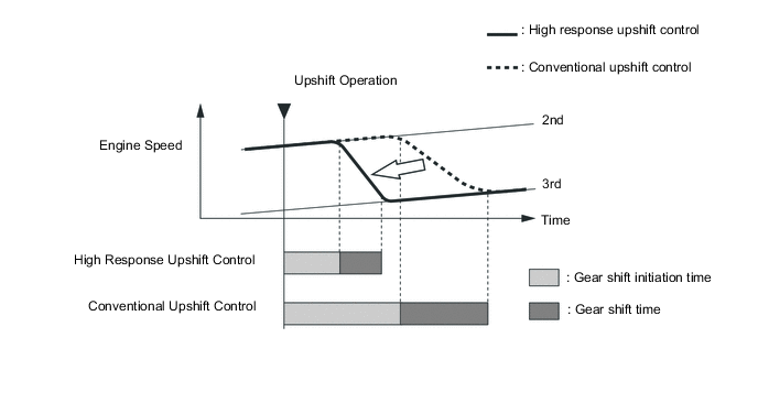
High response upshift control and blipping downshift control are used to improve the responsiveness and feel of shifting gears.
-
Complete lock-up control is used to directly respond to accelerator pedal operations.
-
Gear Hold Control
-
The gear position is held to make it possible to make efficient use of the gear position at maximum engine speeds.
-
Normally, when the system is in M mode, shifting is not performed if the + (UP) and - (DOWN) switches of the paddle shift switch (transmission shift switch) are not operated.
Tech Tips
When an upshift is performed at low speeds, the gear change cannot be performed.
-
The system may automatically shift during M mode in the following situations.
Automatic shifting when the shift lever is in M
-
When the vehicle speed decreases below a specified speed, a downshift is performed.
-
When the ATF or engine coolant temperature is low, gear shifting will be performed automatically.
-
When the ATF temperature is high, gear shifting will be performed automatically.
-
When the needle of the tachometer reaches the red zone (the range beyond the allowable engine speed), gear shifting will be performed automatically.
-
-
-
High Response Upshift Control
-
High response upshift control achieves highly responsive shifting. It does this by using the Driving Response and Acceleration Management System (DRAMS), which integrally controls the engine and transmission, and oil pressure control system, which directly controls the clutch pressure. The oil pressure control system performs quick and precise clutch engagement and release control. The Driving Response and Acceleration Management System (DRAMS) optimally controls the electronic throttle opening angle, ignition timing and fuel injection volume to command the engine torque to decrease. These controls are performed simultaneously to more precisely control engine speed changes when shifting, achieving quick shifting.
-
-
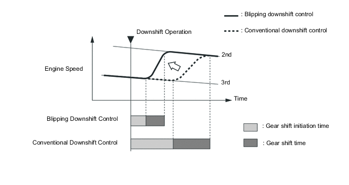
Blipping Downshift Control
-
Blipping downshift control achieves quick shifting in the same manner as high response upshift control by using the oil pressure control system and Driving Response and Acceleration Management System (DRAMS).
-
The oil pressure control system is used to quickly release the clutch and create a neutral condition. Furthermore, the Driving Response and Acceleration Management System (DRAMS) is used to instantly increase the engine speed for synchronizing the engine speed near the gear position speed after shifting. Lastly, the direct oil pressure control system finishes shifting gears by smoothly and quickly engaging the clutch on the engagement side.
Tech Tips
When the ATF and engine coolant temperature is low, blipping downshift control will not be performed.
-
-
Complete Lock-up Control
-
In M mode, engine output changes are transmitted directly to the output shaft by performing complete lock-up control from 2nd gear or higher. As a result, a direct response to accelerator pedal operations is achieved.
-
-
-
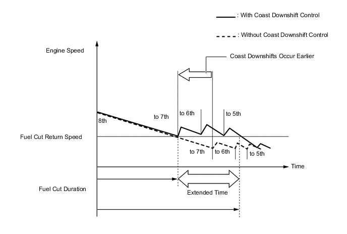
Coast Downshift Control
-
Coast downshift control achieves low fuel consumption by performing fuel cut control as long as possible.
-
When decelerating, flex lock-up clutch control and downshift control are performed to suppress decreases in the engine speed. As a result, the engine speed does not fall below the fuel cut recovery speed, allowing fuel cut control to be performed as long as possible.
-
-
Lock-up Timing Control
-
Lock-up timing control is performed across a wider range to achieve direct drive force transmission and improved fuel efficiency performance.
-
Lock-up timing control is performed when accelerating after decelerating and downshifting to achieve an extremely direct driving feel. In addition to using a torque converter, which uses a multi-plate lock-up clutch, the engine torque and oil pressure are optimally controlled to reduce shocks and improve responsiveness.
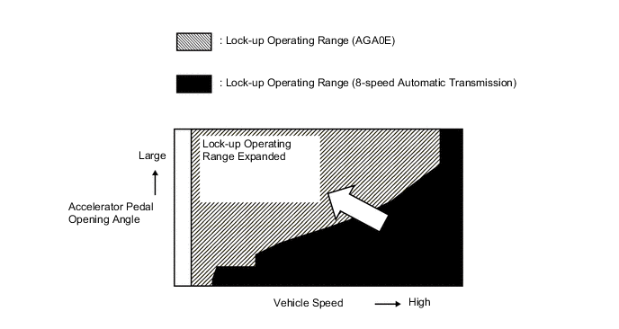
Figure 4. Lock-up Timing Control Operation
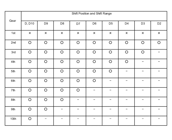
○: Operates
X: Does not operate
-: Not applicable
-
Responsiveness during acceleration is improved by suppressing revving up of the engine speed to achieve a direct driving feel.
-
-
Flex Lock-up Clutch Control
-
Fine-grained control of the drive force transmission distribution using a lock-up clutch (mechanical drive force transmission) and torque convertor (fluid drive force transmission) is performed according to driving conditions to dramatically improve the transmission efficiency.
-
Flex lock-up timing control uses innovative feedback control logic to achieve higher dimensions of system stability and responsiveness in response to a variety of characteristic changes, etc.
Figure 5. Flex Lock-up Timing Control Operation (Acceleration)
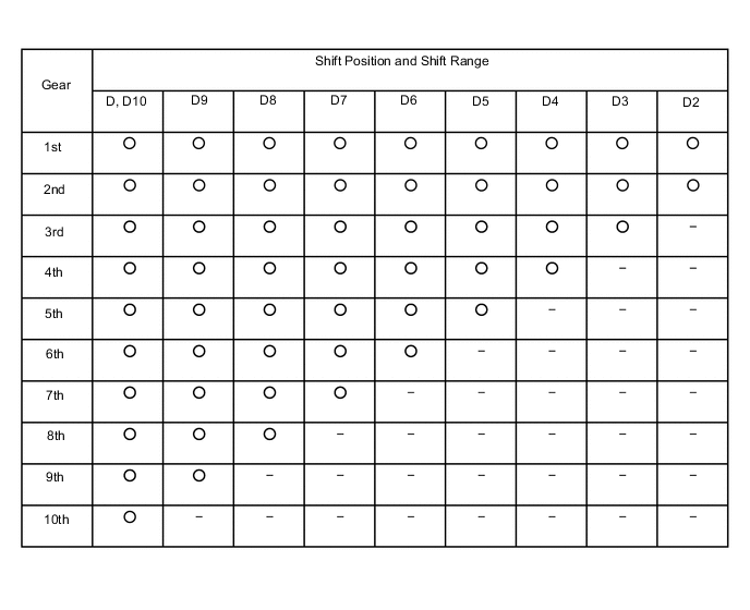
○: Operates
X: Does not operate
-: Not applicable
Figure 6. Flex Lock-up Timing Control Operation (Deceleration)
○: Operates
X: Does not operate
-: Not applicable
-
-
Drive Mode Select
-
This function automatically switches the powertrain control mode between the 5 types selected by drive mode select operations: "Eco", "Normal", "Power"*1 "Power1"*2 and "Power2"*2.
-
SNOW Mode is used to assist driving on surfaces with low friction coefficients, such as snow-covered roads. Throttle characteristics are suppressed and starting off in 2nd gear is supported to suppress sudden drive force changes and ensure driving stability on snow-covered roads.*3
*1: Models without AVS
*2: Models with AVS
*3: Except models for G.C.C. countries
Models with AVS Drive Mode Powertrain Control Mode Outline Normal Normal Ensures fuel economy and driveability when driving in the city, but when driving on winding roads, selects the optimal gear position to provide a more enjoyable driving experience. Comfort Eco Eco Gradually adjusts the throttle characteristics to assist the driver with eco driving. Sport S Power1 This mode is given the control characteristic of selecting a higher speed gear position than Normal mode. As a result, acceleration response and acceleration performance are improved and superior stability is ensured when driving around corners to provide a sportier driving feel when responsiveness and power are required, such as when driving on winding roads with many uphill slopes, downhill slopes and corners. Sport S+ Power2 Selects a higher speed gear position based on information from driver operations (accelerator and brake pedal operations, etc.) and road conditions (road grade, etc.). As a result, acceleration response and acceleration performance are dramatically improved and superior cornering performance is ensured when driving the vehicle at its limits, such as when driving on a race track. Models without AVS Drive Mode Powertrain Control Mode Outline Normal Normal Ensures fuel economy and driveability when driving in the city, but when driving on winding roads, selects the optimal gear position to provide a more enjoyable driving experience. Eco Eco Gradually adjusts the throttle characteristics to assist the driver with eco driving. Sport Power By changing the speed variation point of the transmission from NORMAL mode and controlling the throttle valve opening angle, acceleration and responsiveness are enhanced, supporting sporty driving. In addition, suspension control and steering control are integrated for switching to SPORT mode to improve driveability and stability without sacrificing passenger comfort. As a result, control is performed to enable operations based on the driver's intentions. 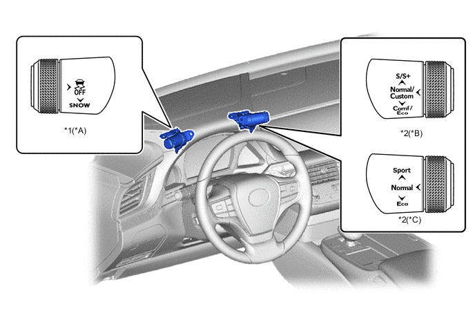
*A Except Models for G.C.C. Countries *B Models with AVS *C Models without AVS - - *1 SNOW Switch (Satellite Switch Set) *2 Drive Mode Select (Satellite Switch Set)
-
-
Artificial Intelligence-shift Control (AI-shift Control)
-
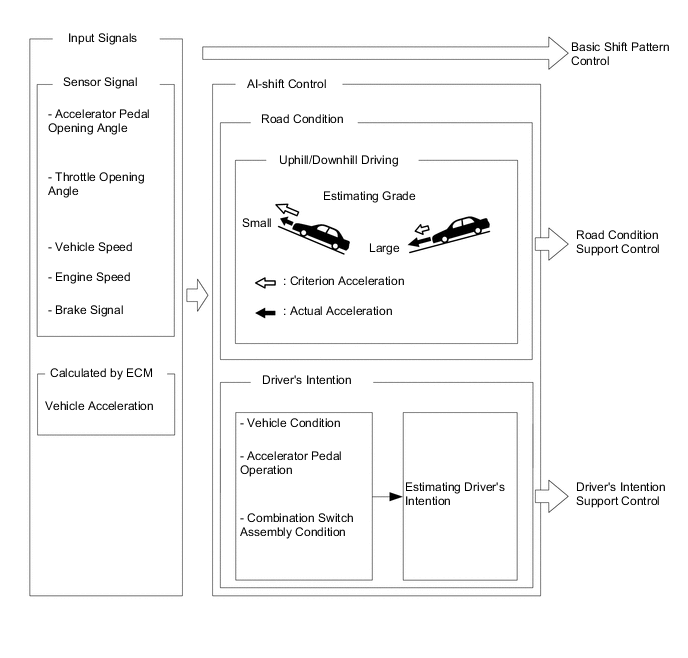
AI-shift control, which automatically switches the shift pattern according to "road conditions" and the "driver's intentions", is used. AI-shift control is used in addition to the normal shift pattern, which takes into consideration the vehicle speed and the engine throttle opening angle as parameters to determine the shift position of the automatic transmission, achieving a higher dimension of comfortable driving.
Tech Tips
AI-shift control will be canceled when M mode or SNOW mode (Except models for G.C.C. countries) is selected.
-
Road Condition Support Control
-
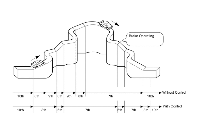
Road condition support control judges whether the vehicle is traveling on an uphill or downhill slope according to information such as the throttle opening angle and vehicle speed. On uphill slopes, unnecessary upshifts are suppressed to constantly achieve the optimal amount of drive force, and on downhill slopes, downshifts are automatically performed to achieve the optimal engine brake force. However, when a paddle shift switch (transmission shift switch) operation is performed during AI-shift control, AI-shift control is canceled and D-range paddle active control is given priority.
-
-
Driver's Intention Support Control
-
Driver intention support control predicts the driver's intentions according to accelerator pedal operations and the vehicle condition and switches to a comfortable shift pattern that is appropriate for the driver without requiring any switch operations.
-
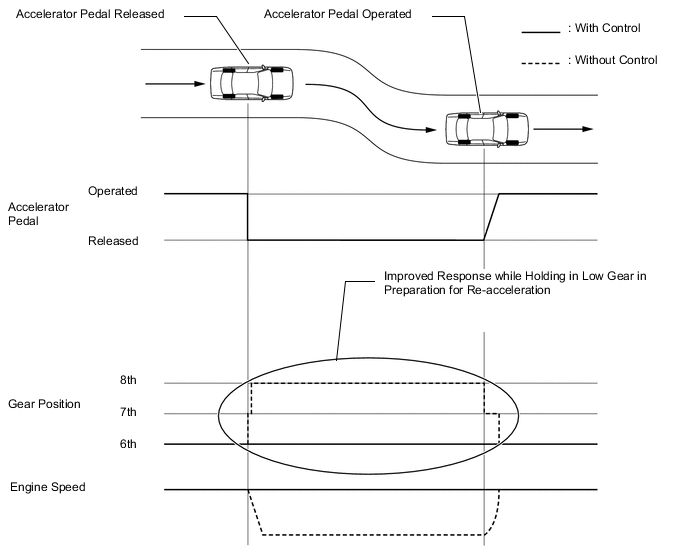
Sudden Accelerator Pedal Release Control
-
When the accelerator pedal is released suddenly, this control makes it easier to hold the gear position, improving responsiveness when reaccelerating and the engine brake force.
-
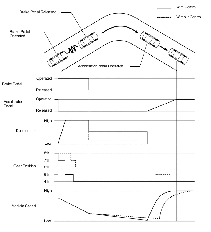
Downshifting Control during Hard Braking
-
High engine braking force and good re-acceleration response have been achieved by actively downshifting during deceleration when hard braking is made.
-
-
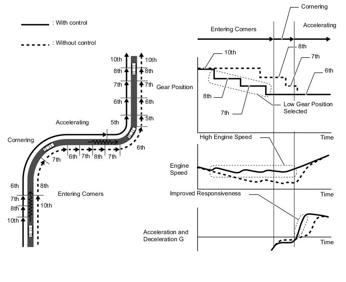
Driver Intention/Driving Scene Support Control
-
Driver intention/driving scene support control selects the optimal gear position according to the driver's intentions and the driving scene at that point in time.
-
When the driver is driving in a relaxed manner, a high gear position is selected to emphasize fuel efficiency.
-
When the driver is driving in a sporty manner, a low gear position is selected to emphasize drive force and responsiveness.
-
Even if the driver has the D range selected while sporty driving is performed on winding roads and race tracks, shifting is performed using a shift pattern that makes it feel like gear positions are being selected manually, achieving a high-speed responsive drive.
Tech Tips
Driver intention/driving scene support control will be canceled when Eco mode is selected.
-
-
-
-
FAIL-SAFE
-
The fail-safe function minimizes the loss of operability when an abnormality occurs in a sensor or a solenoid valve.
-
For details, refer to the Repair Manual.
-
-
DIAGNOSIS
-
When the ECM detects a malfunction, it makes a diagnosis and memorizes the failed section. Furthermore, the ECM illuminates or blinks the MIL in the combination meter assembly to inform the driver.
-
The ECM will also store the Diagnostic Trouble Codes (DTCs) of the malfunctions.
-
The DTCs can be read by connecting the Global TechStream (GTS) to the DLC3.
-
For details, refer to the Repair Manual.
-