STOP AND START
-
CONSTRUCTION
-
The backup boost converter uses a semiconductor relay. The semiconductor relay also functions as a fuse. When overcurrent is detected, the relay is turned off to protect the circuit.
-
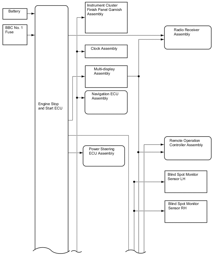
The backup boost converter supplies battery voltage to help make up for the voltage drop that occurs when the engine is restarted. This prevents the operation of the following equipment from being interrupted due to low battery voltage.
-
Instrument Cluster Finish Panel Garnish Assembly
-
Clock Assembly
-
Multi-display Assembly
-
Navigation ECU Assembly
-
Power Steering ECU Assembly
-
Radio Receiver Assembly
-
Remote Operation Controller Assembly
-
Blind Spot Monitor Sensor LH
-
Blind Spot Monitor Sensor RH
-
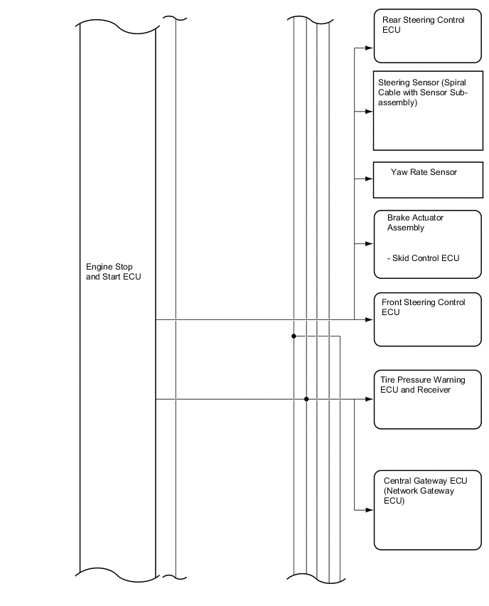
Skid Control ECU (Brake Actuator Assembly)
-
Yaw Rate Sensor
-
Steering Sensor (Spiral Cable with Sensor Sub-assembly)
-
Front Steering Control ECU
-
Rear Steering Control ECU
-
Tire Pressure Warning ECU and Receiver
-
Central Gateway ECU (Network Gateway ECU)
-
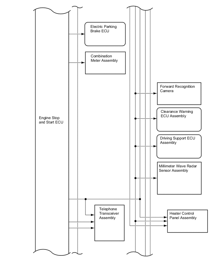
Electric Parking Brake ECU
-
Combination Meter Assembly
-
Telephone Transceiver Assembly
-
Forward Recognition Camera
-
Clearance Warning ECU Assembly
-
Driving Support ECU Assembly
-
Millimeter Wave Radar Sensor Assembly
-
Heater Control Panel Assembly
-
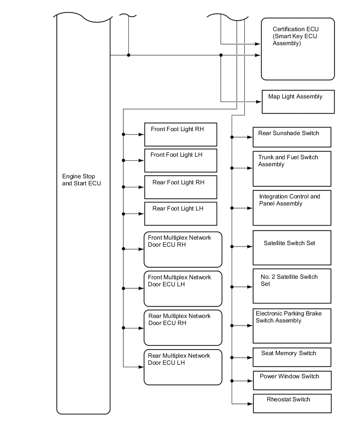
Certification ECU (Smart Key ECU Assembly)
-
Map Light Assembly
-
Front Foot Light RH
-
Front Foot Light LH
-
Rear Foot Light RH
-
Rear Foot Light LH
-
Front Multiplex Network Door ECU RH
-
Front Multiplex Network Door ECU LH
-
Rear Multiplex Network Door ECU RH
-
Rear Multiplex Network Door ECU LH
-
Rear Sunshade Switch
-
Trunk and Fuel Switch Assembly
-
Integration Control and Panel Assembly
-
Satellite Switch Set
-
No. 2 Satellite Switch Set
-
Electric Parking Brake Switch Assembly
-
Seat Memory Switch
-
Power Window Switch
-
Rheostat Switch
Tech Tips
Varies depending on the vehicle specification.
Figure 1. Backup Boost Converter
-
-
An external backup boost converter (eco run vehicle converter assembly) is used.
-
When the audio system is used during idle stop, the external backup boost converter (eco run vehicle converter assembly) compensates for the voltage drop to supplement audio playback by stabilizing the sound quality.
Figure 2. External Backup Boost Converter (Eco Run Vehicle Converter Assembly)
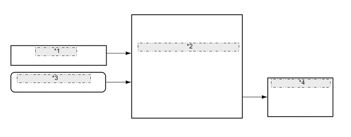
*1 BBC No. 3 Fuse *2 External Backup Boost Converter (Eco Run Vehicle Converter Assembly) *3 Engine Stop and Start ECU *4 Stereo Component Amplifier Assembly
-