LUBRICATION SYSTEM
-
CONSTRUCTION
-
2 oil jets (No. 1 oil nozzle sub-assemblies) are provided for each cylinder. Knocking due to piston temperature increase is suppressed by cooling the exhaust side of the piston.
-
An oil pressure switching valve assembly is used to supply or block oil to the oil jets (No. 1 oil nozzle sub-assemblies).*
-
*: Models with piston jet control system
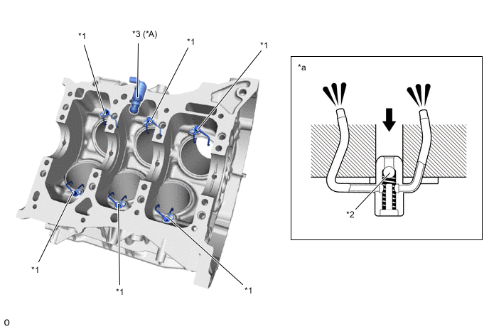
*A Models with Piston Jet Control System - - *1 Oil Jet (No. 1 Oil Nozzle Sub-assembly) *2 Check Valve *3 Oil Pressure Switching Valve Assembly - - *a Oil Jet (No. 1 Oil Nozzle Sub-assembly) Cross Section - - 
Oil - - -
-
-
OPERATION
-
Piston Jet Control System*
-
*: Models with piston jet control system
-
The oil pressure switching valve assembly operates according to signals from the ECM and switches between supplying and shutting off the oil supply to the oil jet (No. 1 oil nozzle sub-assembly) and controls the oil jet (No. 1 oil nozzle sub-assembly) injection.
-
When Injection Is Stopped
-
The valve operates according to signals from the ECM to block the oil passage. As a result, the oil supply to the oil jet (No. 1 oil nozzle sub-assembly) is shut off.
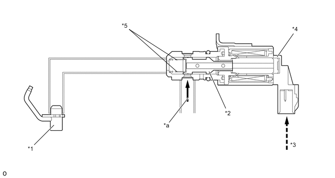
*1 Oil Jet (No. 1 Oil Nozzle Sub-assembly) *2 Valve *3 ECM (Operation Signal) *4 Oil Pressure Switching Valve Assembly *5 Spring - - *a Engine Oil (From Oil Pump) - -
-
-
During Injection
-
The valve is operated by the spring to connect the oil passage to the oil jet (No. 1 oil nozzle sub-assembly) and inject oil.
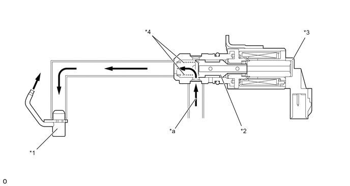
*1 Oil Jet (No. 1 Oil Nozzle Sub-assembly) *2 Valve *3 Oil Pressure Switching Valve Assembly *4 Spring *a Engine Oil (From Oil Pump) - -
-
-
-