COOLANT FLOW
Figure 1. Coolant Path
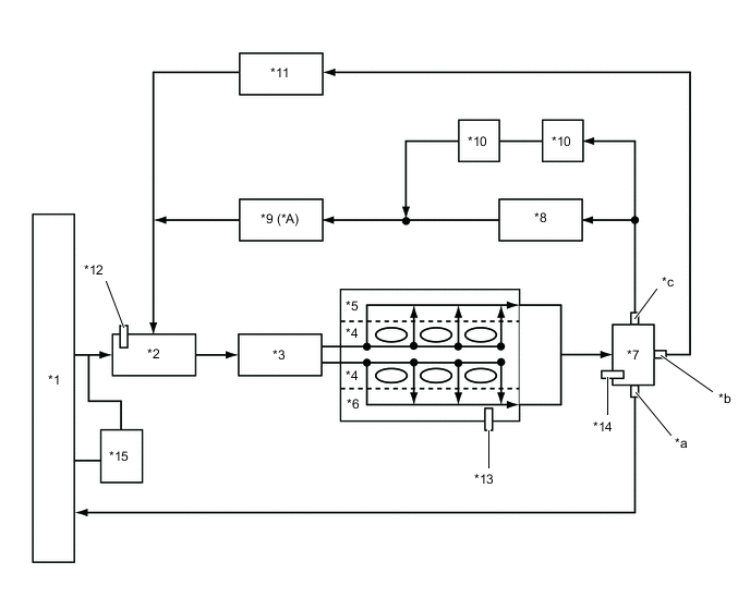
| *A | Models with Stop and Start System | - | - |
| *1 | Radiator Assembly | *2 | Water Inlet |
| *3 | Engine Water Pump Assembly | *4 | Cylinder Block Sub-assembly |
| *5 | Cylinder Head Sub-assembly | *6 | Cylinder Head Sub-assembly LH |
| *7 | Water Control Valve | *8 | Heater Radiator Unit Sub-assembly |
| *9 | Heater Water Pump (Heater Accessory Assembly) | *10 | Throttle Body with Motor Assembly |
| *11 | Oil Cooler Assembly | *12 | Engine Coolant Temperature Sensor (Inlet) |
| *13 | Engine Coolant Temperature Sensor (Cylinder Head Sub-assembly LH) | *14 | Engine Coolant Temperature Sensor (Outlet) |
| *15 | Radiator Reserve Tank Assembly | - | - |
| *a | Radiator Port | *b | ATF Warmer Port |
| *c | Heater Port | - | - |