FUEL SYSTEM
-
CONSTRUCTION
-
A forged iron fuel delivery pipe (for direction injection) is used.
-
A fuel pressure sensor is installed to the No. 2 fuel delivery pipe sub-assembly RH (for direct injection).
-
A nozzle holder clamp is used for the installation area of the direct fuel injector assembly. The nozzle holder clamp constantly pushes the direct fuel injector assembly by the force of the spring to prevent the direct fuel injector assembly from moving when fuel pressure is applied to the direct fuel injector assembly while starting the engine with low fuel pressure. As a result, vibration and noise are reduced while at the same time airtightness is increased.
-
An O-ring seal is used to fasten the fuel pressure sensor (for high pressure) and a metal touch taper seal is used to fasten the fuel pipe (for high pressure).
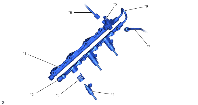
*1 No. 2 Fuel Delivery Pipe Sub-assembly RH (for Direct Injection) *2 No. 2 Fuel Delivery Pipe Sub-assembly LH (for Direct Injection) *3 Nozzle Holder Clamp *4 Direct Fuel Injector Assembly *5 Fuel Pressure Sensor (for High Pressure) *6 No. 1 Fuel Pipe Sub-Assembly *7 No. 2 Fuel Pipe Sub-Assembly *8 No. 3 Fuel Pipe Sub-Assembly
-