ENGINE UNIT
-
CONSTRUCTION
-
A cam that drives the high-pressure fuel pump is positioned in both banks of the exhaust camshaft sub-assembly. Also, a pump cam with 3 peaks is used for the cam that drives the high-pressure fuel pump, and by synchronizing fuel pressure-feeding and fuel injection, the difference in fuel pressure between cylinders is reduced.
-
The stem of the camshaft is made hollow, achieving weight reduction.
-
The cam profile is shaped into a concave curve, increasing valve lift and improving output.
-
A timing rotor, which is used for the camshaft position sensor and has a structure with 3 protrusions, is provided for the intake camshaft sub-assembly and exhaust camshaft sub-assembly.
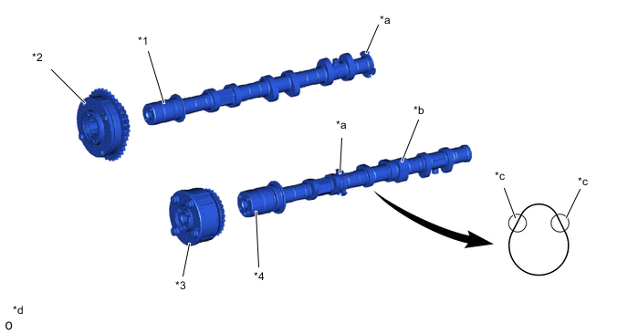
*1 Intake Camshaft Sub-assembly *2 Camshaft Timing Intake Gear Assembly *3 Camshaft Timing Exhaust Gear Assembly *4 Exhaust Camshaft Sub-assembly *a Timing Rotor *b Cam Operating High-pressure Fuel Pump *c Modified Portion of Cam Profile *d The illustration is a representative example.
-