ENGINE UNIT
-
CONSTRUCTION
-
On the intake side, Variable Valve Timing-intelligent by Electric motor (VVT-iE), a continuously variable valve timing mechanism that operates the electric motor to control the intake camshaft to the optimal valve timings according to driving conditions, is used.
-
On the exhaust side, Variable Valve Timing-intelligent (VVT-i), a continuously variable valve timing mechanism that operates the fuel pressure to control the exhaust camshaft to the optimal valve timings according to driving conditions, is used.
-
The valve rocker arm sub-assembly is used as a valve mechanism and by achieving size reduction while drastically reducing the amount of friction that occurs between the sliding parts and cams, low fuel economy is achieved. Also, an oil pressure type valve lash adjuster assembly is used to make valve clearance adjustment unnecessary in consideration of serviceability.
-
A beehive shape that narrows the upper part of the valve spring (cylinder head intake valve compression spring and cylinder head exhaust valve compression spring) is used, reducing inertial mass. As a result, the load on the valve spring and friction are reduced.
-
The valve spring retainer diameter is reduced, reducing inertial mass and friction.
-
The outer diameter and thickness of the valve stem cap are optimized and the entire size is reduced, reducing friction.
-
The exhaust valves ensure valve cooling performance and reliability by using sodium as a refrigerant. Holes are provided in the valve stems and sodium with high heat conductance and a low melting point is included to support high exhaust temperatures. Also, the valve stems are made hollow to achieve weight reduction and reduce friction.
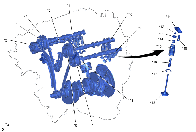
*1 Intake Camshaft Sub-assembly RH *2 Exhaust Camshaft Sub-assembly RH *3 No. 2 Chain Sub-assembly (RH) *4 Camshaft Timing Intake Gear Assembly RH *5 Camshaft Timing Exhaust Gear Assembly RH *6 Camshaft Timing Intake Gear Assembly LH *7 Camshaft Timing Exhaust Gear Assembly LH *8 No. 2 Chain Sub-assembly (LH) *9 Exhaust Camshaft Sub-assembly LH *10 Intake Camshaft Sub-assembly LH *11 Valve rocker Arm Sub-Assembly *12 Valve Stem Cap *13 Cylinder Head Valve Spring Retainer *14 Cylinder Head Intake (Exhaust) Valve Stem Oil Seal *15 Cylinder Head Intake (Exhaust) Valve Compression Spring *16 Valve Guide Bush *17 Cylinder Head Valve Spring Seat *18 Cylinder Head Intake (Exhaust) Valve *19 Valve Rush Adjuster Assembly - - *a The illustration is a representative example. - - Valve Timing Intake Valve Open 65° to -20° BTDC Close 5° to 90° ABDC Exhaust Valve Open 60° to 16° BBDC Close 0° to 44° ATDC 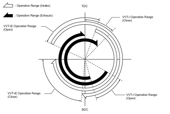
-