ENGINE UNIT
-
CONSTRUCTION
-
A cast-iron liner with a die-cast aluminum coating is used for the cylinder block sub-assembly, achieving weight and size reduction.
-
Spiny processing is used for the outer circumference of the cylinder liner (cast iron) to achieve increased closeness with the cylinder bore (aluminum) and improved heat dissipation performance, reducing the piston temperature and suppressing bore deformation.
-
The angle of the bore cross hatching used to polish the surface of the cylinder liner is set to 30°, ensuring oil maintenance performance. As a result, friction is reduced between the cylinder bore and piston, improving fuel efficiency.
-
The thickness of the cylinder bore, the shape of the water jacket and the outer wall ribs are optimized, achieving weight reduction and ensuring high rigidity and reliability.
-
The thickness of the outer wall is reduced to 2.3 mm, achieving weight reduction.
-
The size of the cylinder head bolt is optimized.
-
A drill passage (coolant path) is provided between each bore to reduce the temperature between the bores, achieving high engine output and ensuring oil consumption performance.
-
Breathing holes are provided in the journal walls between cylinders to reduce air moving resistance inside the crankcase, reducing friction in the high-speed range.
-
A PCV separator chamber is provided between the V banks to create a compact structure that ensures ventilation performance.
-
Parallel high pressure oil paths (main oil gallery and sub oil gallery) are built into the cylinder block sub-assembly.
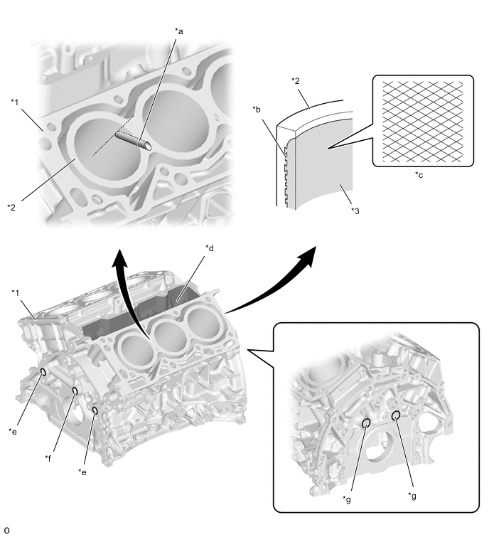
*1 Cylinder Block Sub-assembly *2 Cylinder Bore *3 Cylinder Liner - - *a Drill Passage (Coolant Path) *b Spiny-type Cylinder Liner *c Bore Cross Hatch *d PCV Separator Chamber *e Sub Oil Gallery *f Main Oil Gallery *g Air Passage Hole - -
-