ENGINE UNIT
-
CONSTRUCTION
-
A pent-roof combustion chamber is used to position the spark plugs almost directly in the center of the combustion chamber, improving combustion efficiency and anti-knock performance.
-
The shape of the intake port, injector spray pattern and shape of the combustion chamber have been optimized to improve combustion efficiency.
-
A laser cladded valve seat is used to optimize the shape of the intake port and increase the intake air volume and tumble flow, achieving high engine output and low fuel consumption.
-
A valve lash adjuster assembly, which is integrated with the oil supply passage that runs to it, is positioned on the upper portion of the cylinder head.
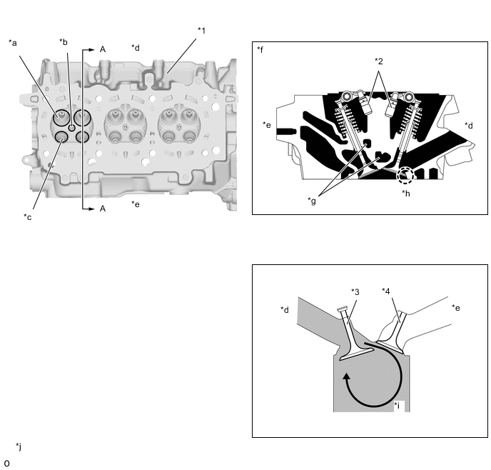
*1 Cylinder Head Sub-assembly *2 Valve Lash Adjuster Assembly *3 Intake Valve *4 Exhaust Valve *a Intake Port *b Spark Plug Hole *c Exhaust Port *d Intake Side *e Exhaust Side *f A-A Cross Section *g Water Jacket *h Laser Cladded Valve Seat *i Tumble Flow *j The illustration is a representative example. -
The cam journal is split into a 2-part structure and a simple structure is used for the cylinder head sub-assembly, achieving weight reduction and improving serviceability.
-
A die-cast aluminum camshaft housing sub-assembly is used to achieve weight reduction.
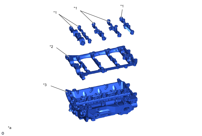
*1 Camshaft Bearing Cap *2 Camshaft Housing Sub-assembly LH *3 Cylinder Head Sub-assembly LH - - *a The illustration is a representative example. - - -
The exhaust manifold is built into the cylinder head to achieve size and weight reduction. The exhaust ports have a structure that positions them inside the cylinder head and delivers exhaust gas into the turbocharger sub-assembly. The positioning of the exhaust ports achieves low emissions and improved engine output performance.
-
The length and diameter of the exhaust ports are optimized, achieving improved engine output performance and exhaust cooling performance.
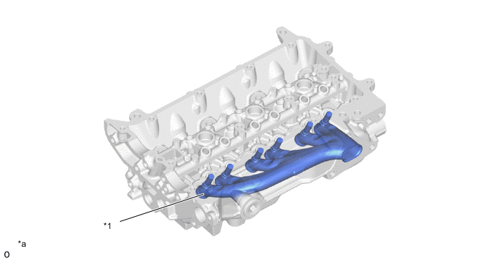
*1 Exhaust Manifold - - *a The illustration is a representative example. - - -
A 2-stage structure is used for the water jacket inside the cylinder head and coolant is concentrated in the bottom of the water jacket to enhance the cooling of the combustion chamber. In addition, the wall between the upper and lower water jackets is reinforced to support the high pressure and heat load increase due to supercharging.
-
The shape of the water jacket is optimized, lowering the temperature of the combustion chamber and minimizing the temperature difference between the cylinders. As a result, high compression, high torque, high engine output and low fuel consumption are achieved.
-
The water jacket inside the cylinder head cools the exhaust manifold integrated into the cylinder head to cool the exhaust gas and reduce the temperature of the exhaust gas flowing through the turbocharger sub-assembly, ensuring reliability and expanding the driving range at the stoichiometric air-fuel ratio.
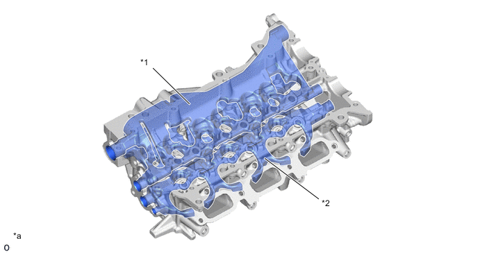
*1 Water Jacket (Upper Side) *2 Water Jacket (Lower Side) *a The illustration is a representative example. - -
-