EVAPORATIVE EMISSION CONTROL SYSTEM(w/ Canister Pump Module)
-
FUNCTION OF MAIN COMPONENTS
-
The main components of the evaporative emission control system are as follows:
Component Function Charcoal Canister Assembly Canister Contains activated charcoal to adsorb the fuel vapor that is created in the fuel tank assembly. Fuel Outlet Valve Assembly Trap Canister Canister Pump Module (Leak Detection Pump Sub-assembly) Vent Valve Opens and closes the fresh air line in accordance with signals from the ECM. Leak Detection Pump and Pump Motor Applies vacuum to the evaporative emission system in accordance with signals from the ECM. Canister Pressure Sensor Detects the pressure in the evaporative emission system and sends the signals to the ECM. Fresh Air Line Fresh air goes into the canister and the cleaned air goes out into the atmosphere. Purge VSV (Duty Vacuum Switching Valve Assembly) Opens in accordance with the signals from the ECM when the system is purging in order to send the fuel vapor that was adsorbed by the canister into the intake manifold. In system monitoring mode, this valve controls the introduction of vacuum into the fuel tank assembly. No. 2 Turbo Pressure Sensor Detects the pressure inside the hose to monitor purge flow of each bank. No. 1 Check Valve Prevents intake air from flowing back toward the canister due to the turbo pressure. No. 1 Charcoal Canister Filter Prevents dust and debris from entering the system. ECM Controls the canister pump module and the purge VSV (duty vacuum switching valve assembly), in accordance with the signals from various sensors in order to achieve a purge volume that suits the driving conditions. In addition, the ECM monitors the system for any leaks and stores a DTC if a malfunction is found.
-
-
OPERATING CONDITION
-
The following are the typical conditions necessary to enable an evaporative emission leak check:
Typical Enabling Conditions
-
5 hours have elapsed after the engine has been turned off*.
-
Altitude: Below 2400 m (8000 ft.)
-
Battery Voltage: 10.5 V or more
-
Engine Switch: Off
-
Engine Coolant Temperature: 4.4 to 35°C (40 to 95°F)
-
Intake Air Temperature: 4.4 to 35°C (40 to 95°F)
-
*: If the engine coolant temperature does not drop below 35°C (95°F), this time is extended to 7 hours. After that, if the temperature is not less than 35°C (95°F), the time is extended to 9.5 hours.
Tech Tips
-
The canister pump module performs a fuel evaporative emission leak check. This check is performed approximately 5 hours after the engine is turned off. Sound may be heard coming from underneath the luggage compartment for several minutes. This does not indicate a malfunction.
-
A pinpoint pressure test procedure is performed by pressurizing the fresh air line that runs from the canister pump module to the No. 1 charcoal canister filter neck. For details, refer to the repair manual.
-
-
-
-
SYSTEM CONTROL
-
Purge Flow Control
-
When the engine has reached a predetermined state [closed loop, engine coolant temperature above 80°C (176°F), etc.], stored fuel vapor is purged from the charcoal canister assembly whenever the purge VSV (duty vacuum switching valve) is opened by the ECM.
-
The ECM changes the duty ratio cycle of the purge VSV (duty vacuum switching valve), thus controlling purge flow volume. Purge flow volume is determined by the intake manifold pressure and the duty ratio cycle of the purge VSV (duty vacuum switching valve). Atmospheric pressure is allowed into the charcoal canister assembly to ensure that purge flow is constantly maintained whenever purge vacuum is applied to the charcoal canister assembly.
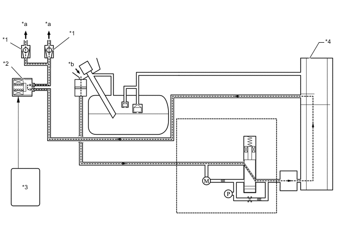
*1 No. 1 Check Valve *2 Purge VSV (Duty Vacuum Switching Valve) (Open) *3 ECM *4 Charcoal Canister Assembly *a To Intake Manifold *b Atmosphere
-
-
Onboard Refueling Vapor Recovery (ORVR)
-
When the internal pressure of the fuel tank assembly increases during refueling, the fuel vapor enters the charcoal canister assembly. The air that has had the fuel vapor removed from it will be discharged through the fresh air line. The vent valve is used to open and close the fresh air line, and it is always open (even when the engine is stopped) except when the vehicle is in monitoring mode (the valve will remain open as long as the vehicle is not in monitoring mode). If the vehicle is refueled in system monitoring mode, the ECM will recognize the refueling by way of the canister pressure sensor, which will detect the sudden pressure increase in the fuel tank assembly, and the ECM will open the vent valve.
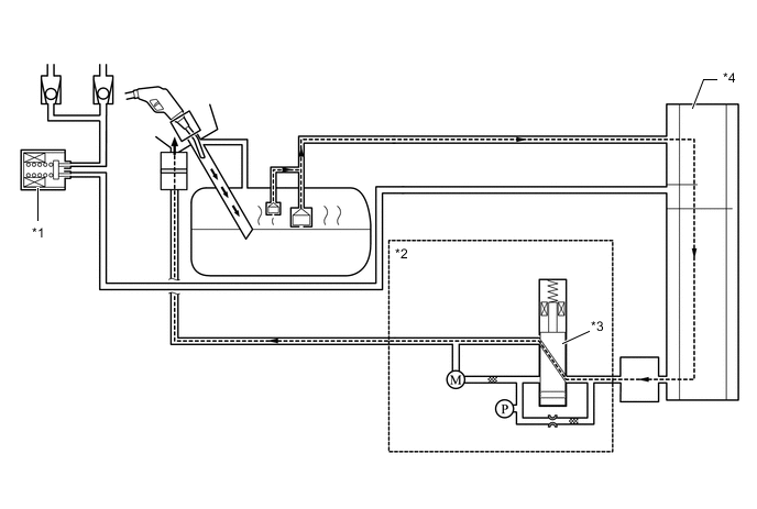
*1 Purge VSV (Duty Vacuum Switching Valve) (Closed) *2 Canister Pump Module *3 Vent Valve *4 Charcoal Canister Assembly
-
-
EVAP Leak Check
-
General
-
Approximately 5 hours after the engine switch has been turned off, the ECM operates the canister pump module to detect any evaporative emission leakage occurring between the fuel tank assembly and the charcoal canister assembly through changes in the fuel tank assembly pressure.
-
The EVAP leak check operates in accordance with the following timing chart:
Figure 1. Timing Chart
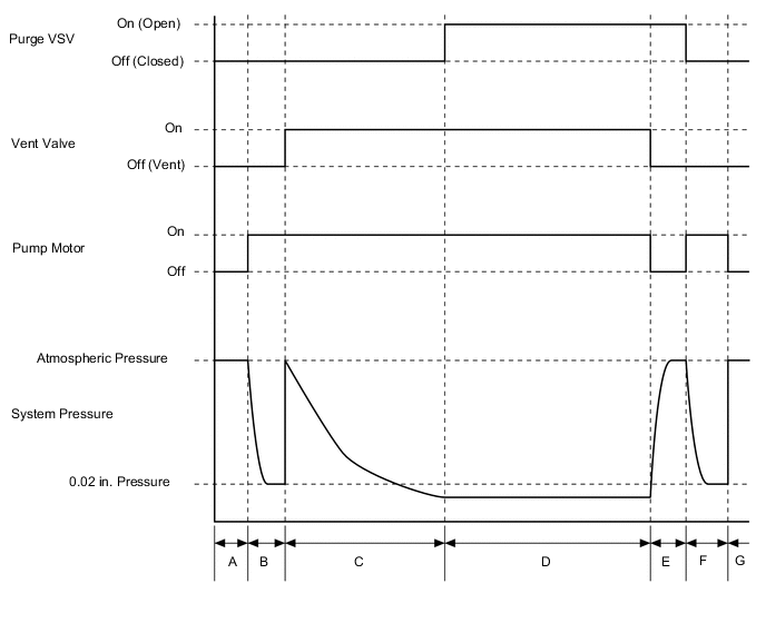
Order Operation Description Time A Atmospheric Pressure Measurement The ECM turns the vent valve off (vent) and measures EVAP system pressure to determine the atmospheric pressure. 60 sec. B 0.02 in. Leak Pressure Measurement The leak detection pump creates negative pressure (vacuum) limited by a 0.02 in. orifice, and the pressure is measured. The ECM determines this as the 0.02 in. leak pressure (reference pressure). 360 sec. C EVAP Leak Check The leak detection pump creates negative pressure (vacuum) in the EVAP system and the EVAP system pressure is measured. If the stabilized pressure is larger than the 0.02 in. leak pressure, the ECM determines that the EVAP system has a leak. If the EVAP pressure does not stabilize within 15 minutes, the ECM cancels the EVAP monitor. Within 15 min. D No. 1 Check Valve Monitoring The ECM opens the purge VSV (duty vacuum switching valve) and measures the EVAP pressure. If the pressure does not change, ECM interprets this as normal. 20 sec. E Vent Valve Monitoring The ECM opens the purge VSV (duty vacuum switching valve) and measures the EVAP pressure increase. If the increase is large, the ECM interprets this as normal. 10 sec. F Repeat 0.02 in. Leak Pressure Measurement The leak detection pump creates negative pressure (vacuum) limited by a 0.02 in. orifice and the pressure is measured. The ECM determines this as the 0.02 in. leak pressure. 60 sec. G Final Check The ECM measures the atmospheric pressure and records the monitor result. -
-
-
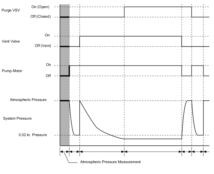
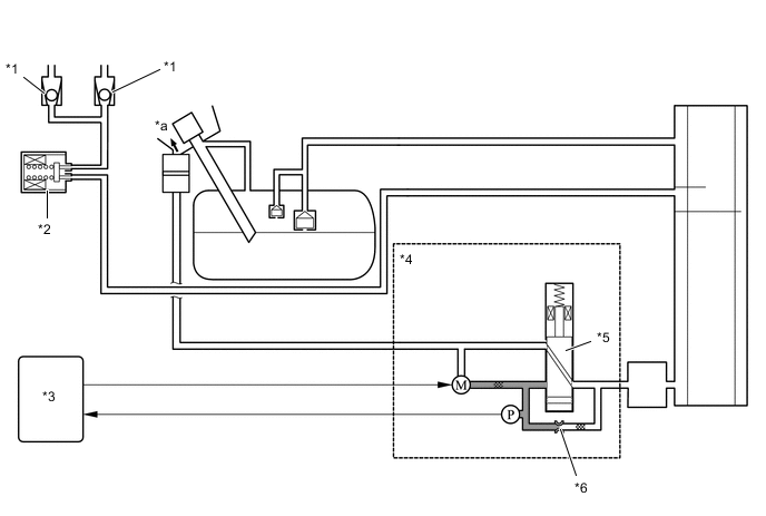
Atmospheric Pressure Measurement
-
When the engine switch is turned off, the purge VSV (duty vacuum switching valve) and the vent valve are turned off. Therefore, atmospheric pressure is introduced into the charcoal canister assembly.
-
The ECM measures the atmospheric pressure using the canister pressure sensor.
-
If the measured atmospheric pressure is out of range, the ECM actuates the leak detection pump in order to monitor the changes in the pressure.
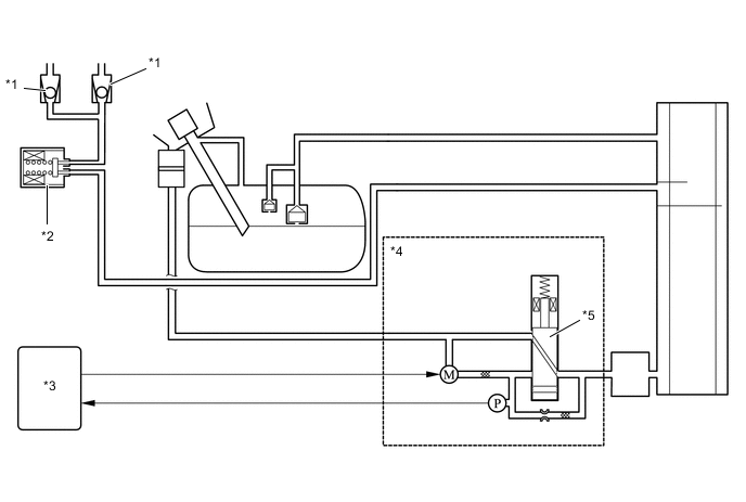
*1 No. 1 Check Valve *2 Purge VSV (Duty Vacuum Switching Valve) (Off) *3 ECM *4 Canister Pump Module *5 Vent Valve (Off) - - Figure 2. Timing Chart
-
-
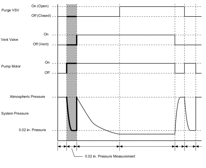
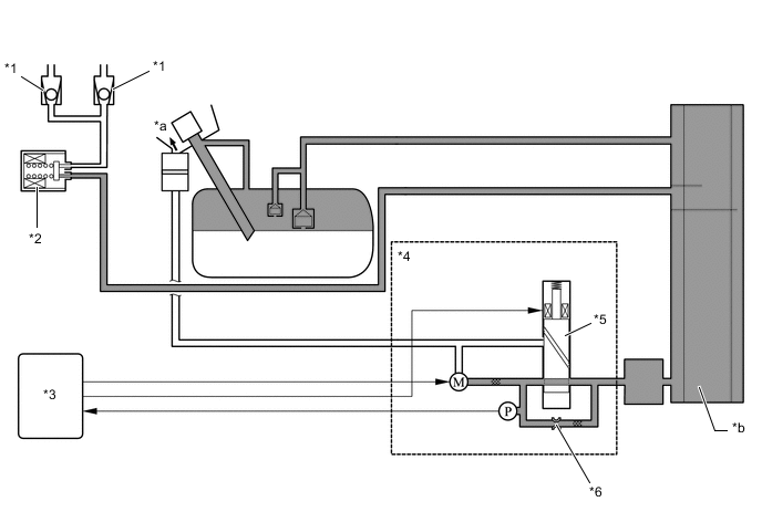
0.02 in. Leak Pressure Measurement
-
The purpose of this measurement is to confirm leak detection pump operation, and to provide a baseline measurement value that is used for comparison in subsequent leak test steps.
-
The vent valve remains off, atmospheric pressure is introduced into the charcoal canister assembly and the ECM actuates the leak detection pump, creating a vacuum in the piping close to the canister pressure sensor.
-
At this time, the pressure will not decrease below what is referred to as the 0.02 in. pressure due to the atmospheric pressure that enters the piping close to the pump and sensor through the 0.02 in. diameter reference orifice.
-
The ECM compares its standard and this pressure. If the pressure is within the acceptable range, the ECM stores this pressure as the 0.02 in. leak pressure.
-
If the pressure is below the standard, the ECM will determine that the reference orifice is clogged and store DTC in its memory.
-
If the pressure is above the standard, the ECM will determine that a high flow rate pressure is passing through the reference orifice and store DTCs in its memory.
-
If the pressure does not reach the predetermined pressure within 4 seconds, the ECM will determine it abnormal and store DTC in its memory.
*1 No. 1 Check Valve *2 Purge VSV (Duty Vacuum Switching Valve) (Off) *3 ECM *4 Canister Pump Module *5 Vent Valve (Off) *6 Reference Orifice *a Atmosphere - - Figure 3. Timing Chart
-
-
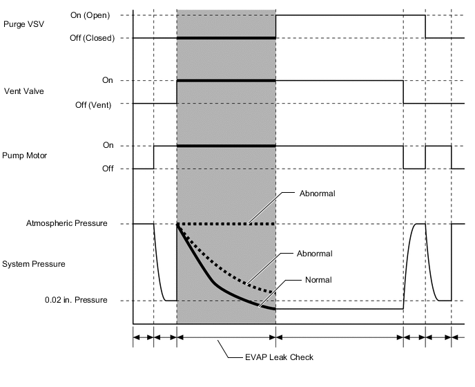
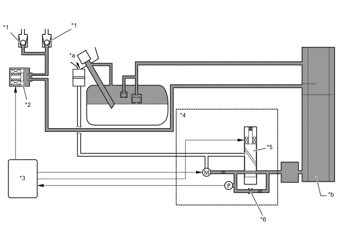
EVAP Leak Check
-
While actuating the leak detection pump, the ECM turns the vent valve on in order to introduce a vacuum into the charcoal canister assembly.
-
When the pressure in the system stabilizes, the ECM compares this pressure and the 0.02 in. pressure in order to determine if a leak is present.
-
If the detected pressure is below the 0.02 in. pressure, the ECM determines that there is no leak.
-
If the detected pressure is above the 0.02 in. pressure and near atmospheric pressure, the ECM determines that there is a gross leak (large hole) and stores DTC in its memory.
-
If the detected pressure is above the 0.02 in. pressure, the ECM determines that there is a small leak (minor leak) and stores DTC in its memory.
*1 No. 1 Check Valve *2 Purge VSV (Duty Vacuum Switching Valve) (Off) *3 ECM *4 Canister Pump Module *5 Vent Valve (On) *6 Reference Orifice *a Atmosphere *b Vacuum Figure 4. Timing Chart
-
-
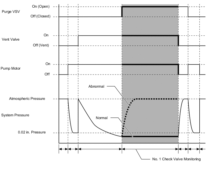
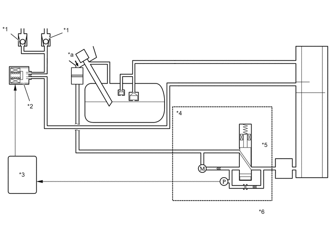
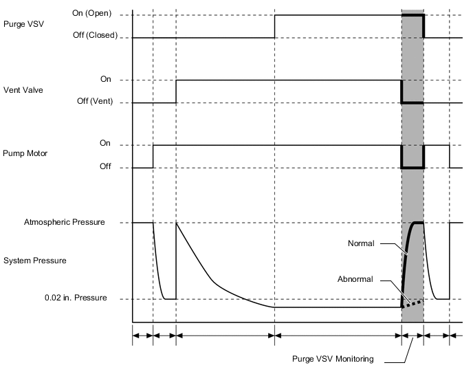
No. 1 Check Valve Monitoring
-
After completing an EVAP leak check, the ECM turns the purge VSV (duty vacuum switching valve) on (open) with the leak detection pump actuated.
-
If pressure does not change, the ECM determines the condition to be normal.
-
If pressure changes, the ECM will stop the No. 1 check valve monitoring and store DTC in its memory.
*1 No. 1 Check Valve *2 Purge VSV (Duty Vacuum Switching Valve) (On) *3 ECM *4 Canister Pump Module *5 Vent Valve (On) *6 Reference Orifice *a Atmosphere *b Vacuum Figure 5. Timing Chart
-
-
Vent Valve Monitoring
-
After completing the No. 1 check valve monitoring, the ECM turns the vent valve and leak detection pump off, and introduces the atmospheric pressure from the fuel inlet to the charcoal canister assembly.
-
If the pressure change at this time is within the normal range (a pressure change occurs), the ECM determines the condition to be normal.
-
If the pressure change is out of the normal range (insufficient pressure change occurs), the ECM will stop the purge VSV (duty vacuum switching valve) monitoring (purge monitoring) and store DTC in its memory.
*1 No. 1 Check Valve *2 Purge VSV (Duty Vacuum Switching Valve) (On) *3 ECM *4 Canister Pump Module *5 Vent Valve (On) *6 Reference Orifice *a Atmosphere - - Figure 6. Timing Chart
-
-
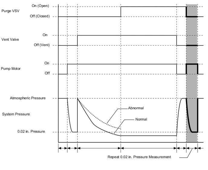
Repeat 0.02 in. Leak Pressure Measurement
-
While the ECM operates the leak detection pump, the purge VSV (duty vacuum switching valve) and vent valve are turned off and a repeat 0.02 in. leak pressure measurement is performed.
-
The ECM compares the measured pressure with the pressure during the EVAP leak check.
-
If the pressure during the EVAP leak check is less than the repeat 0.02 in. leak pressure measurement, the ECM determines that there is no leak.
-
If the pressure during the EVAP leak check is above the repeat 0.02 in. leak pressure measurement, the ECM determines that there is a small leak and stores DTC in its memory.
*1 No. 1 Check Valve *2 Purge VSV (Duty Vacuum Switching Valve) (Off) *3 ECM *4 Canister Pump Module *5 Vent Valve (Off) *6 Reference Orifice *a Atmosphere - - Figure 7. Timing Chart
-
-
-