SFI SYSTEM
Figure 1. LHD Models
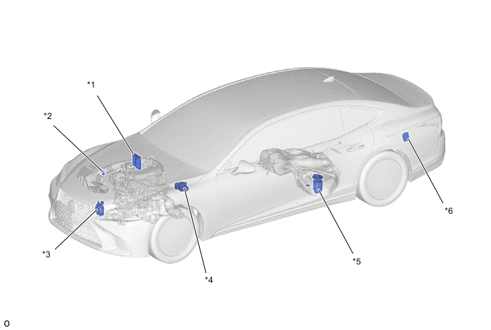
| *1 | ECM | *2 | Intake Mass Air Flow Meter Sub-assembly
|
| *3 | Cooling Fan Motor (Built-in Cooling Fan Controller) | *4 | Brake Actuator Assembly
|
| *5 | Fuel Suction Tube with Pump and Gauge Assembly
|
*6 | Fuel Pump Control ECU Assembly |
Figure 2. RHD Models
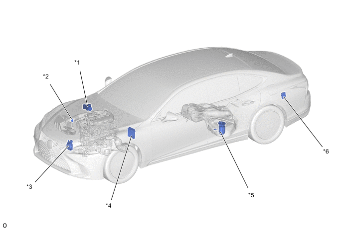
| *1 | Brake Actuator Assembly
|
*2 | Intake Mass Air Flow Meter Sub-assembly
|
| *3 | Cooling Fan Motor (Built-in Cooling Fan Controller) | *4 | ECM |
| *5 | Fuel Suction Tube with Pump and Gauge Assembly
|
*6 | Fuel Pump Control ECU Assembly |
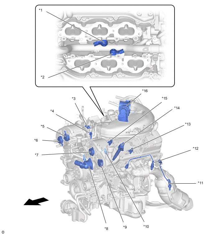
| *1 | Knock Control Sensor (Bank 1) | *2 | Knock Control Sensor (Bank 2) |
| *3 | Fuel Pressure Sensor (for Low Pressure) | *4 | Fuel Injector Assembly (for Port Injection) |
| *5 | Cam Timing Oil Control Solenoid Assembly (Bank 1 Intake) | *6 | Cam Timing Oil Control Solenoid Assembly (Bank 1 Exhaust) |
| *7 | Cam Timing Oil Control Solenoid Assembly (Bank 2 Intake) | *8 | Water Inlet with Thermostat Sub-assembly
|
| *9 | Cam Timing Oil Control Solenoid Assembly (Bank 2 Exhaust) | *10 | Fuel Injector Assembly (for Direct Injection) |
| *11 | Air Fuel Ratio Sensor (Bank 2, Sensor 2) | *12 | Air Fuel Ratio Sensor (Bank 2, Sensor 1) |
| *13 | Cam Position Sensor (No. 2 Crank Position Sensor) (Bank 2, Exhaust) | *14 | Ignition Coil Assembly |
| *15 | Cam Position Sensor (No. 2 Crank Position Sensor) (Bank 2, Intake) | *16 | Throttle Body with Motor Assembly
|
 |
Vehicle Front | - | - |
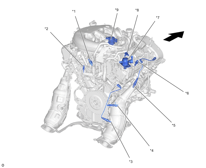
| *1 | Fuel Pressure Sensor (for High Pressure) | *2 | Engine Coolant Temperature Sensor |
| *3 | Air Fuel Ratio Sensor (Bank 1, Sensor 2) | *4 | Crank Position Sensor |
| *5 | Air Fuel Ratio Sensor (Bank 1, Sensor 1) | *6 | Cam Position Sensor (No. 2 Crank Position Sensor) (Bank 1, Exhaust) |
| *7 | Fuel Pump Assembly (for High Pressure) | *8 | Cam Position Sensor (No. 2 Crank Position Sensor) (Bank 1, Intake) |
| *9 | Purge VSV (No. 1 Vacuum Switching Valve Assembly) | - | - |
| |
Engine Front | - | - |
Figure 3. LHD Models

| *A | Models with Headup Display | - | - |
| *1 | Certification ECU (Smart Key ECU Assembly) | *2 | ID Code Box (Immobiliser Code ECU) |
| *3 | Headup Display (Meter Mirror Sub-assembly) | *4 | No. 2 Combination Switch Assembly
|
| *5 | Combination Meter Assembly | *6 | Stop Light Switch Assembly |
| *7 | Accelerator Pedal Sensor Assembly | *8 | DLC3 |
| *9 | Paddle Shift Switch (Transmission Shift Switch Assembly) | *10 | Steering Pad Switch Assembly (for Cruise Control) |
| *11 | Airbag Sensor Assembly | *12 | Yawrate Sensor (Built-in Acceleration Sensor) |
| *13 | Combination Switch Assembly
|
*14 | Air Conditioning Amplifier Assembly |
| *a | Refer to Service Bulletin for the installation position of the part. | - | - |
Figure 4. RHD Models
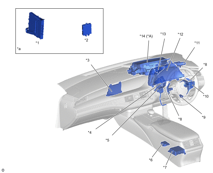
| *A | Models with Headup Display | - | - |
| *1 | Certification ECU (Smart Key ECU Assembly) | *2 | ID Code Box (Immobiliser Code ECU) |
| *3 | Air Conditioning Amplifier Assembly | *4 | Stop Light Switch Assembly |
| *5 | Accelerator Pedal Sensor Assembly | *6 | Yawrate Sensor (Built-in Acceleration Sensor) |
| *7 | Airbag Sensor Assembly | *8 | Paddle Shift Switch (Transmission Shift Switch Assembly) |
| *9 | DLC3 | *10 | Steering Pad Switch Assembly (for Cruise Control) |
| *11 | No. 2 Combination Switch Assembly
|
*12 | Combination Meter Assembly |
| *13 | Combination Switch Assembly
|
*14 | Headup Display (Meter Mirror Sub-assembly) |
| *a | Refer to Service Bulletin for the installation position of the part. | - | - |