BODY STRUCTURE
-
CONSTRUCTION
-
Sound Absorption and Insulation Structure
-
Various types of silencers are positioned around the floor panel and engine compartment to greatly suppress vibration and noise that are transmitted into the interior from parts such as the engine and tires, achieving superior quietness. Also, materials such as foamed materials, sound insulation sealant and damping materials are optimally positioned to achieve superior NVH*performance.
Tech Tips
*: An abbreviation created by taking the first letter of Noise (unpleasant sounds and loud sounds), Vibration (vibrations from the engine and tires) and Harshness (vibrations felt through the steering wheel, seats and floor according to height changes in the road surface, etc.). NVH is used to describe the level of riding comfort and sound quality actually experienced by passengers.
-
-
Floor Silencer
-
The floor silencer (applied damping materials) optimal thickness varies by the area, is lightweight and provides excellent quietness. These characteristics allow the floor silencer to reduce road and engine noise which enters the cabin.
-
In what put out for coating of the thickness of the damping materials, I planned improvement of the silent nature and coexistence of the Mass reduction. (the constant coating ratio: approximately 900 g decrease)
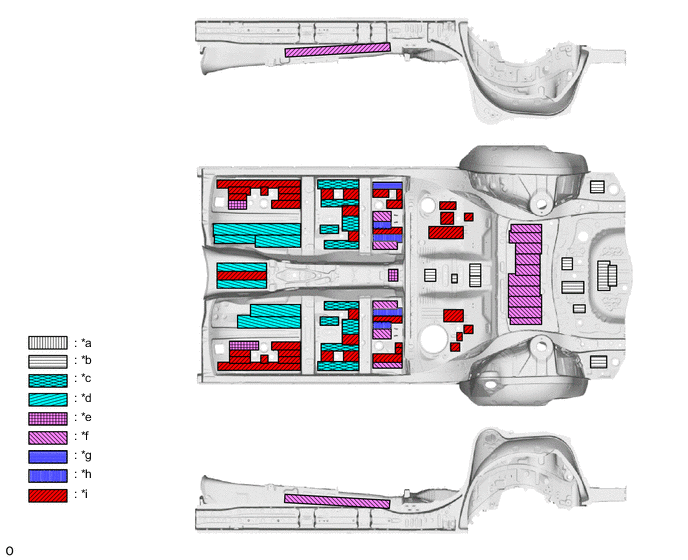
*a 2.0 mm (0.08 in.) *b 2.5 mm (0.10 in.) *c 3.0 mm (0.12 in.) *d 3.5 mm (0.14 in.) *e 4.0 mm (0.16 in.) *f 4.5 mm (0.18 in.) *g 5.0 mm (0.20 in.) *h 5.5 mm (0.22 in.) *i 6.0 mm (0.24 in.) - -
-
-
Sealing Material
-
Foamed materials, NV covers and sponge sealant are optimally placed in the side member opening and front header to suppress wind noise and road noise which enter the cabin.
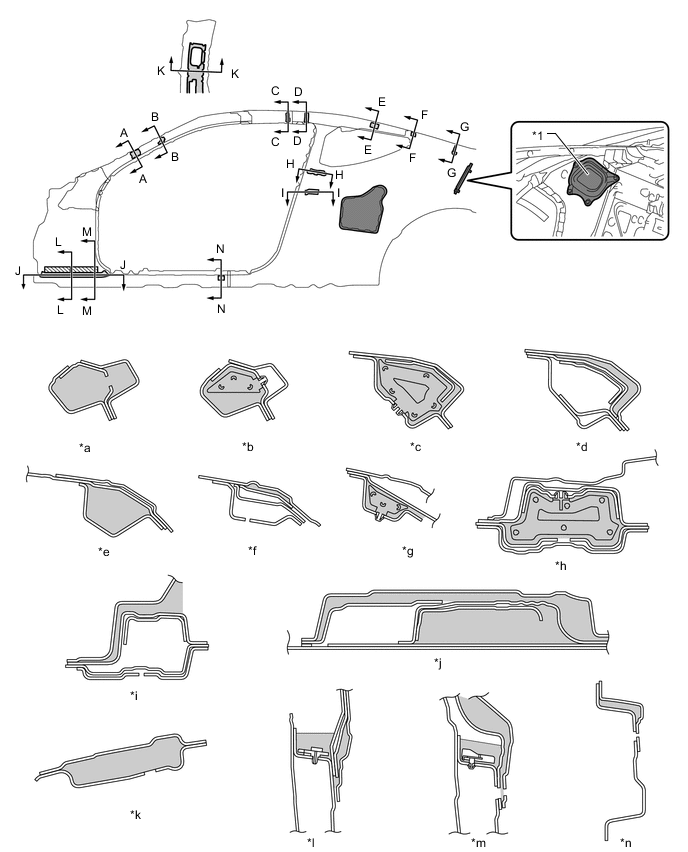
*1 Quarter Service Hole Cover No. 2 LH - - *a A - A Cross Section *b B - B Cross Section *c C - C Cross Section *d D - D Cross Section *e E - E Cross Section *f F - F Cross Section *g G - G Cross Section *h H - H Cross Section *i I - I Cross Section *j J - J Cross Section *k K - K Cross Section *l L - L Cross Section *m M - M Cross Section *n N - N Cross Section 
Foamed Material 
Sponge 
NV Cover - -
-
-
Floor Panel Sheet Thickness Optimization
-
Connecting rigidity and panel thickness are increased in areas close to passengers to suppress panel vibrations. As a result, superior riding comfort is ensured.
-
The toe board reinforcement (*1 in illustration) is connected to part of the rocker (front floor reinforcement (*2 in illustration)) to suppress panel vibrations.
-
The front floor pan (*3 in illustration) uses different thickness tailored blank material. The sheet thickness is increased where passengers place their feet to suppress panel vibrations.
-
The front floor panel CTR (*4 in illustration) uses different thickness tailored blank material. The sheet thickness is increased around the transmission to suppress panel vibrations.
-
Thick sheets are used in the dash panel sub-assembly (*5 in illustration) to suppress panel vibrations.
-
-
A heavy underbody structure is used to achieve a low center of gravity and improve the sense of material quality. Also, steel cabin parts are used to achieve stable mode control during collisions.
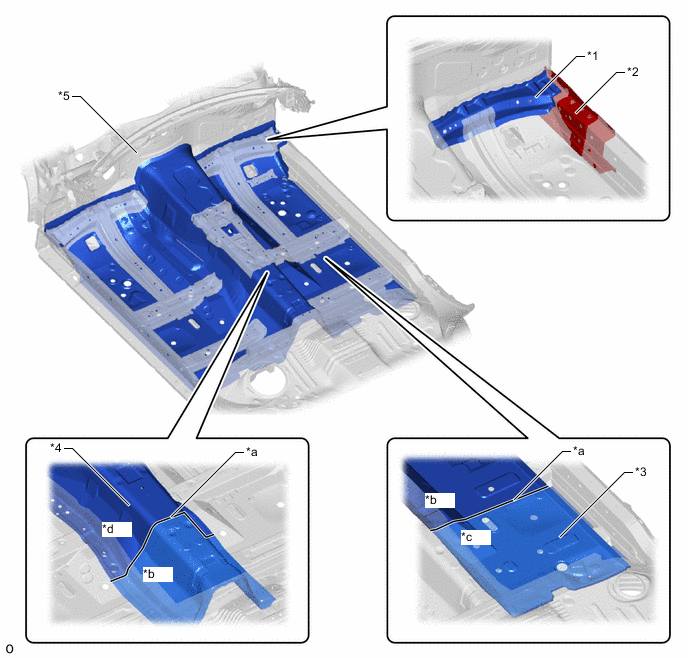
*1 Toe Board Reinforcement RH *2 Front Floor Reinforcement RH *3 Front Floor Pan RH *4 Front Floor Panel CTR *5 Dash Panel Sub-assembly - - *a Tailored Blank Line *b Sheet Thickness: 1.2 mm (0.05 in.) *c Sheet Thickness: 0.7 mm (0.03 in.) *d Sheet Thickness: 1.4 mm (0.06 in.)
-
-
Sound Absorption and Insulation Structure around Engine Compartment
-
The dash panel insulator outer is provided in the engine compartment side of the dash panel sub-assembly and a dash panel insulator assembly is provided in the cabin side. This structure absorbs and insulates mechanical noise such as engine noise and ensures excellent quietness.
-
The dash panel insulator assembly uses a 3-layered construction that reduces the opening ratio*and ensures thickness to ensure superior sound absorption and insulation performance.
Tech Tips
*: Opening area ratio for the entire area of the insulator
Figure 1. Dash Panel Insulator Outer
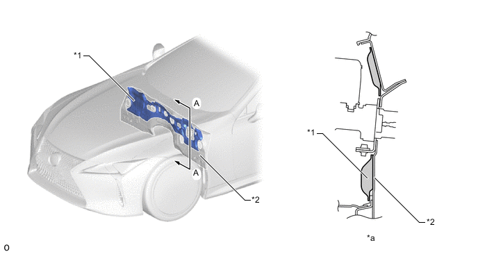
*1 Dash Panel Insulator Outer *2 Dash Panel Sub-assembly *a A - A Cross Section - - Figure 2. Dash Panel Insulator Assembly
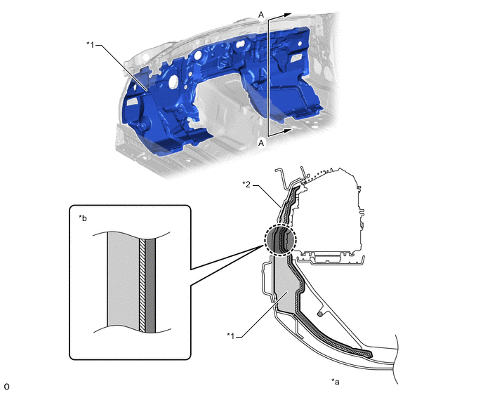
*1 Dash Panel Insulator Assembly *2 Dash Panel Sub-assembly *a A - A Cross Section *b Material Structure Urethane Olefin Sheet Felt - -
-
-
A hood insulator is provided on the rear of the hood sub-assembly. This achieves excellent sound insulation performance
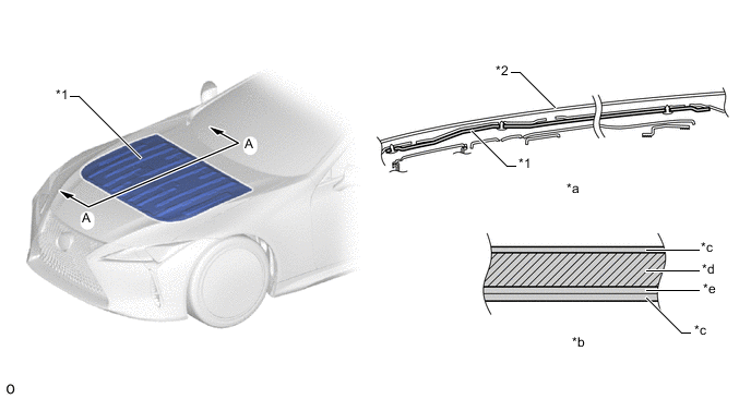
*1 Hood Insulator *2 Hood Sub-assembly *a A - A Cross Section *b Material Structure *c Non-woven Fabric *d Urethane Foam *e Spunbond - - -
Service Hole (Front Door Panel Inside)
-
The front door panel inside is designed to require only one service hole, reducing the amount of outside noise that enters the cabin through the doors.
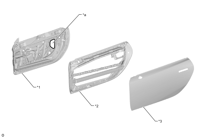
*1 Front Door Panel Inside LH *2 Front Door Hinge Side Panel LH *3 Front Door Panel Outside LH - - *a Service Hole - -
-
-
Sound Generator
-
The engine intake air sound is passed through the intake air sound creator (*2 in illustration), the sound is introduced into the cowl top reinforcement inner (*5 in illustration) and resonance is utilized, expressing an emotional engine sound that spreads throughout the interior.
Tech Tips
Sound Generator:
A system that adds an uplifting harmony, which pierces far and wide according to increases in the engine speed, to the engine sound. The system achieves this by tuning the sound generated by the intake air sound creator (*2 in illustration), which uses engine intake air pulsations, and the resonance frequency of the front and rear connecting hoses to create a unique sound across three different high-frequency registers.
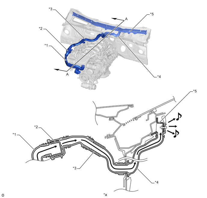
*1 Intake Air Connector Pipe *2 Intake Air Sound Creator *3 Intake Air Connector Pipe No. 2 *4 Intake Air Connector Pipe No. 3 *5 Cowl Top Reinforcement Inner - - *a A - A Cross Section - - 
Sound Flow - -
-
-