BODY STRUCTURE
-
CONSTRUCTION
-
Aero Parts
-
While paying close attention to the vehicle's styling, aerodynamic parts, which reduce air resistance, increase airflow adjustment effects, achieve driving stability, suppress lift and increase quietness, are positioned everywhere to achieve the driving pleasure of a sports coupe.
-
-
Front Bumper
-
Air from the front is directed from the side grille in the front bumper cover to the wheel arch to allow the airflow to pass through, reducing air resistance.
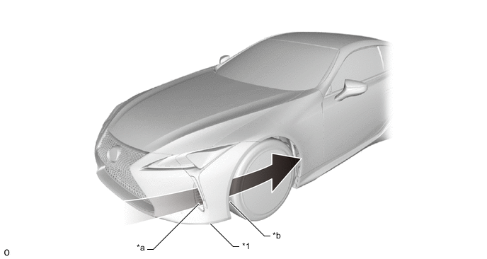
*1 Front Bumper Cover - - *a Side Grille *b Front Wheel Arch 
Airflow - -
-
-
Front Spats
-
The surface area of the front spat (front wheel opening extension pad) is optimized to ensure superior aerodynamic performance.
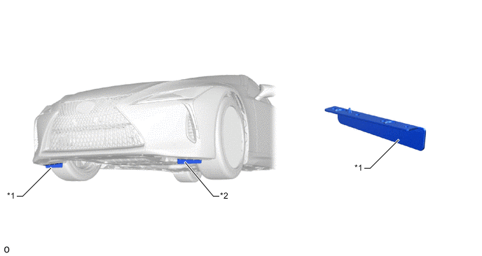
*1 Front Wheel Opening Extension Pad RH *2 Front Wheel Opening Extension Pad LH
-
-
Front Fender Liner
-
A slit hole is provided in the front fender liner to provide a release for the negative pressure inside the front bumper, ensuring superior aerodynamic performance.
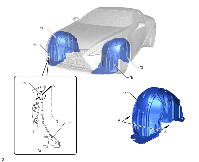
*1 Front Fender Liner RH *2 Front Fender Liner LH *a A - A Cross Section *b Slit Hole Airflow - -
-
-
Aero Stabilizing Fin
-
An aero stabilizing fin is provided in the front door front lower frame cover upper. The air flowing over the aero stabilizing fin generates spiral turbulence behind the fin. This turbulence suppresses air separation from the side of the body, reduces air resistance (the resistance due to the negative pressure that occurs behind physical objects) and laterally presses against the vehicle to ensure superior driving stability.
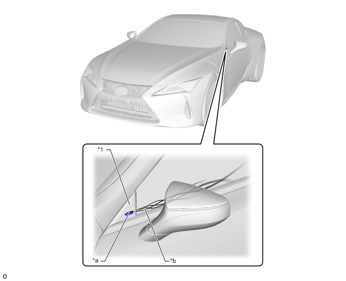
*1 Front Door Front Lower Frame Cover Upper LH - - *a Aero Stabilizing Fin *b Turbulence
-
-
Body Rocker Panel Molding Assembly
-
An air duct (opening shape) is provided in the body rocker panel molding assembly. Air is directed into this air duct to suppress the air separation that occurs as a result of the air resistance generated by the difference in level of the outer panel surface of the body rocker panel molding assembly.
-
The air flowing out of the air duct is directed over the side surface of the rear tire to suppress air turbulence, ensuring superior driving stability.
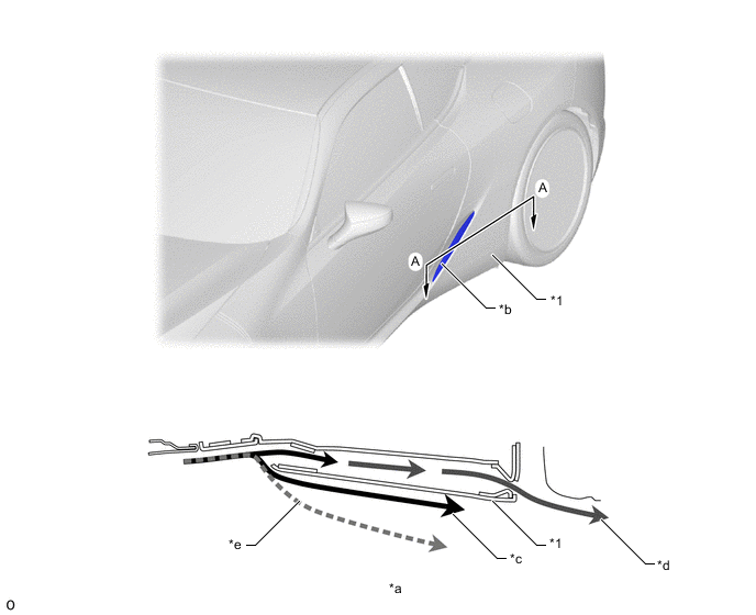
*1 Body Rocker Panel Molding Assembly LH - - *a A - A Cross Section *b Air Duct *c Air Passing outside Air Duct Pulled Inwards to Flow along Rocker Molding Side Surface *d Air Passing inside Air Duct Adjusted to Flow Over Rear Tire Side Surface *e Air Separation - -
-
-
Rear Wheel House Plate Front/Rear Wheel House Liner
-
A rear wheel house plate front is provided in front of rear wheel house liner, with the aim of suppressing the air volume hitting against the rotating bodies of the tires. As a result, turbulence generated by the rotation of the rear tires, which disturbs airflow around the rear tires, has been suppressed, reducing air resistance and ensuring a high level of straight-line stability at a high speed by adjusting the airflow.
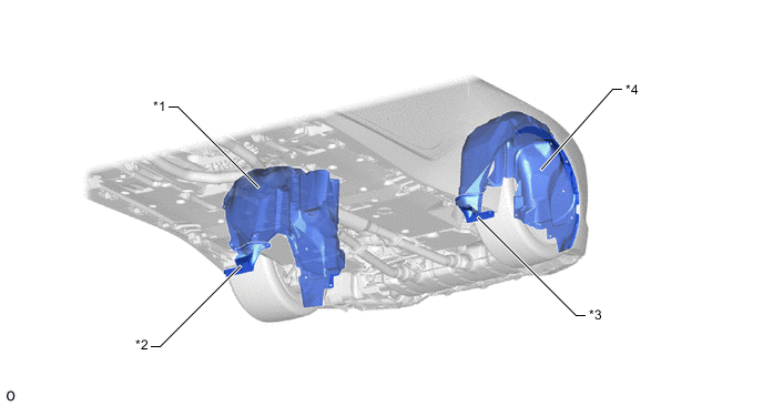
*1 Rear Wheel House Liner RH *2 Rear Wheel House Plate Front RH *3 Rear Wheel House Plate Front LH *4 Rear Wheel House Liner LH
-
-
Luggage Compartment Panel Shape
-
The rear end portion of the luggage compartment door panel sub-assembly has been given a sharp shape, aiming for air resistance reduction by smoothly introducing airflow from the roof to the rear.
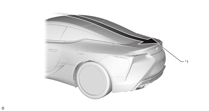
*1 Luggage Compartment Door Panel Sub-assembly - - Airflow - -
-
-
Under Cover
-
The body rocker panel molding assemblies (*18 and *19 in illustration) are positioned so that they overlap the under cover (*c in illustration). This expands the under cover floor cover range and reduces air resistance of flattened floor components and the under cover, improving fuel efficiency.
-
Aero stabilizing fins are optimally positioned on the underside of the vehicle to adjust the air flowing under the vehicle and effectively generate downforce.
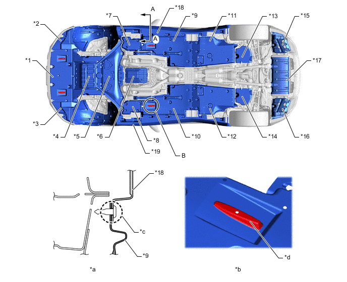
*1 Engine Under Cover Assembly No. 1 *2 Front Fender Liner LH *3 Front Fender Liner RH *4 Strut Bar Bracket Support Sub-assembly *5 Engine Under Cover Assembly No. 2 *6 Transmission Oil Pan *7 Front Fender Seal LH *8 Front Fender Seal RH *9 Front Floor Cover LH *10 Front Floor Cover RH *11 Rear Floor Side Member Cover LH *12 Rear Floor Side Member Cover RH *13 Differential Support Protector No. 2 *14 Differential Support Protector No. 1 *15 Rear Bumper Side Support No. 4 LH *16 Rear Bumper Side Support No. 4 RH *17 Main Muffler Assembly *18 Body Rocker Panel Molding Assembly LH *19 Body Rocker Panel Molding Assembly RH - - *a A - A Cross Section *b Enlarged Illustration of B *c Overlap Area *d Aero Stabilizing Fin
-
-
Rear Bumper
-
The rear bumper is shaped to smoothly direct the air flowing up from under the vehicle to lower air resistance and ensure superior driving stability.
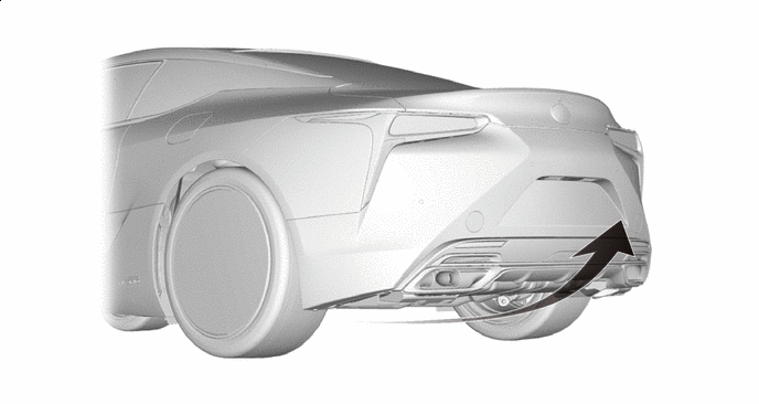
Airflow - -
-
-
Aluminum Tape
-
Aluminum tape (molding tape No. 1) is provided on the back of the front bumper cover and rear bumper cover. The body and air become positively charged when driving, making it easier for the air to separate from the body. Aluminum tape that effectively discharges the electrical charge of the vehicle is optimally positioned because air separation generates turbulence and prevents aerodynamic effects. As a result, nearby air separation is suppressed, ensuring superior operational stability.
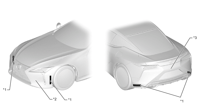
*1 Molding Tape No. 1 *2 Front Bumper Cover *3 Rear Bumper Cover - -
-
-