AIR CONDITIONING SYSTEM
-
CONSTRUCTION
-
An air conditioning unit that is compatible with left and right independent temperature control is used.
-
A Beneficial Refrigerant Stream (BRS) type evaporator is used.
-
A Straight Flow Aluminum-II (SFA-II) heater core that is compact and offers advanced performance is used.
-
A pollen and odor-removing type clean air filter (air refiner element) is provided as standard equipment.
Figure 1. Air Conditioning Unit Layout Parts Location
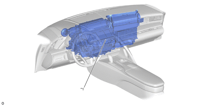
*1 Air Conditioning Unit Assembly - - Figure 2. Duct Layout Parts Location
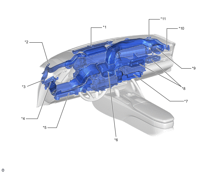
*1 Front Defroster Duct *2 Driver Side Front Defroster Duct *3 Driver Side Side Defroster Duct *4 Driver Side Side Register Duct *5 Driver Side Footwell Register Duct *6 Driver Side Center Register Duct *7 Front Passenger Side Footwell Register Duct *8 Front Passenger Side Center Register Duct *9 Front Passenger Side Register Duct *10 Front Passenger Side Side Defroster Duct *11 Front Passenger Side Front Defroster Duct - -
-
-
OPERATION
-
Mode Position and Door Operation
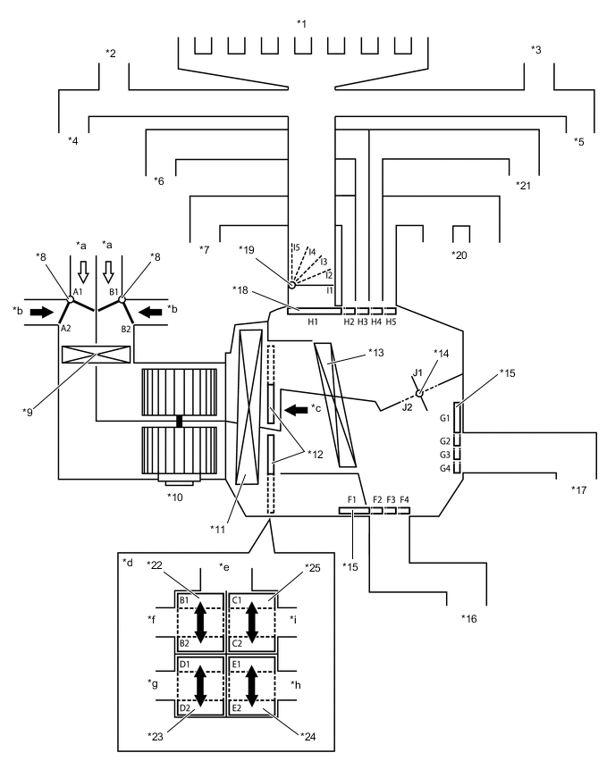
*1 Front Defroster *2 Driver Side Front Defroster *3 Front Passenger Side Front Defroster *4 Driver Side Side Defroster *5 Driver Side Side Register *6 Front Passenger Side Side Defroster *7 Driver Side Center Register *8 Air Inlet Control Door *9 Air Refiner Element (Clean Air Filter) *10 Blower Motor with Fan Sub-assembly *11 No. 1 Cooler Evaporator Sub-assembly *12 Air Mix Control Damper *13 Heater Radiator Unit Sub-assembly *14 Inside-and-outside Dual Air Layer Control Door *15 Mode Control Door (for FOOT Door) *16 Driver Side Footwell Register Duct *17 Front Passenger Side Footwell Register Duct *18 Mode Control Door (for FACE Door) *19 Mode Control Door (for DEF Door) *20 Front Passenger Side Center Register *21 Front Passenger Side Side Register *22 Mode Control Door (for Driver Side Upper Layer Air Mix Door) *23 Mode Control Door (for Driver Side Lower Layer Air Mix Door) *24 Mode Control Door (for Passenger side Lower Layer Air Mix Door) *25 Mode Control Door (for Passenger side Upper Layer Air Mix Door) - - *a Recirculated Air *b Fresh Air *c Illustration Image View from [A] *d [A] View *e To Center and Side Defrosters *f To Driver Side Center and Side Registers *g To Driver Side Footwell Register Duct *h To Front Passenger Side Footwell Register Duct *i To Front Passenger Side Center and Side Registers - - Functions of Main Dampers Control Damper Operation Position Damper Position Operation Air Inlet Control Damper FRESH A1, B1 Allows fresh air to enter. RECIRCULATION A2, B2 Causes internal air to recirculate. Inside-and-outside Dual Air Layer Control Door - (Auto Control) J1 - J2 Separates or integrates the upper layer and lower layer in response to the control conditions to control the inside-and-outside dual air layers. Air Mix Control Damper MAX COLD to MAX HOT Temperature Setting B1 - B2
C1 - C2
D1 - D2
E1 - E2
Varies the front passenger side mixture ratio of the fresh air and the recirculation air in order to regulate the temperature continuously from HI to LO. Air Outlet Control Damper FACE U F4, G4, H1, I1 Air blows out of the center registers and side registers. FACE L F3, G3, H2, I1 Air blows out of the center and side registers. In addition, air blows out slightly from the footwell register ducts. FACE R F4, G4, H3, I1 Air blows out of the center registers and side registers. BI-LEVEL F2, G2, H4, I1 to I2 Air blows out of the center registers, side registers and footwell register ducts. Air may blow out from the front defroster and side defrosters depending on the cabin environment (I2). FOOT D F2, G2, H4, I3 Air blows out of the front defroster, side defrosters and footwell register ducts. In addition, air blows out slightly from the center and side registers. FOOT R F2, G2, H4, I2 Air blows out of the footwell register ducts. In addition, air blows out slightly from the front defroster, side defrosters and center registers and side registers. FOOT F F1, G1, H4, I2 Air blows out of the footwell register ducts. In addition, air blows out slightly from the front defroster, side defrosters, center registers and side registers. FOOT/DEF F2, G2, H4, I4 Defrosts the windshield through the front defroster, side defrosters, footwell register ducts, center registers and side registers. DEF F4, G4, H5, I5 Defrosts the windshield through the front and side defrosters. Figure 3. Air Outlets and Airflow Volume
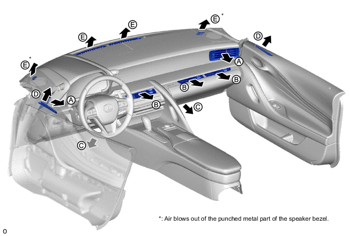
Air Outlet Mode Mode A B C D E Register Footwell Defroster Auto Manual Side Center Front Side Main FACE U 

/ / / FACE L - 

/ / FACE R - 
/ / / B/L 
FOOT D - FOOT R FOOT F - FOOT/DEF DEF - / / / *: Air may blow out from the defroster in response to the cabin temperature and moisture, and outside temperature conditions.
-