PARKING ASSIST MONITOR SYSTEM
-
FUNCTION OF MAIN COMPONENTS
Component Function Television Camera Assembly
-
Captures images of the area behind the vehicle.
-
The parking assist guide lines that are calculated based on signals from the steering sensor are superimposed on the captured image. Then, the image is sent to the multi-display.
-
When the luggage compartment door is open, superimposing of parking assist guide lines is canceled and only the captured image is sent to the multi-display.
Multi-display Receives visual signals composed of the area behind the vehicle with parking assist guide lines overlaid from the television camera assembly, and displays them. Radio Receiver Assembly Sends signals indicating a mode change in parking guide line display functions to the television camera assembly. Steering Sensor Detects the angle of the steering wheel and sends the resulting signals to the television camera assembly. Main Body ECU (Multiplex Network Body ECU) Sends the luggage compartment door courtesy switch signal to the television camera assembly. Clearance Warning ECU Assembly Sends the Lexus parking assist-sensor system information signal to the television camera assembly. Blind Spot Monitor Sensor RH*1 Sends the RCTA function information signal to the television camera assembly. ECM Sends the shift position signal to the television camera assembly. No. 3 Semiconductor Power Integration ECU Sends the reverse signal to the multi-display. FR Steering Control ECU*2 Sends the VGRS signal to the television camera assembly. Central Gateway ECU (Network Gateway ECU) Relays the signal between the CAN communication buses. DLC3 The Global TechStream (GTS) can be connected to read the Diagnostic Trouble Codes (DTCs) of malfunctions. *1: Models with blind spot monitor system
*2: Models with Lexus dynamic handling system
-
-
SYSTEM CONTROL
-
The parking assist monitor system operates when both of the following conditions are met:
-
The engine switch is on (IG).
-
The shift position is R.
-
-
-
FUNCTION
-
Area Displayed on Screen
-
Objects on the right of the vehicle appear on the right side of the multi-display, and objects on the left of the vehicle appear on the left side of the multi-display.
-
The television camera assembly uses a wide-angle lens. The perceived distance from images that appear on the screen differs from the actual distance.
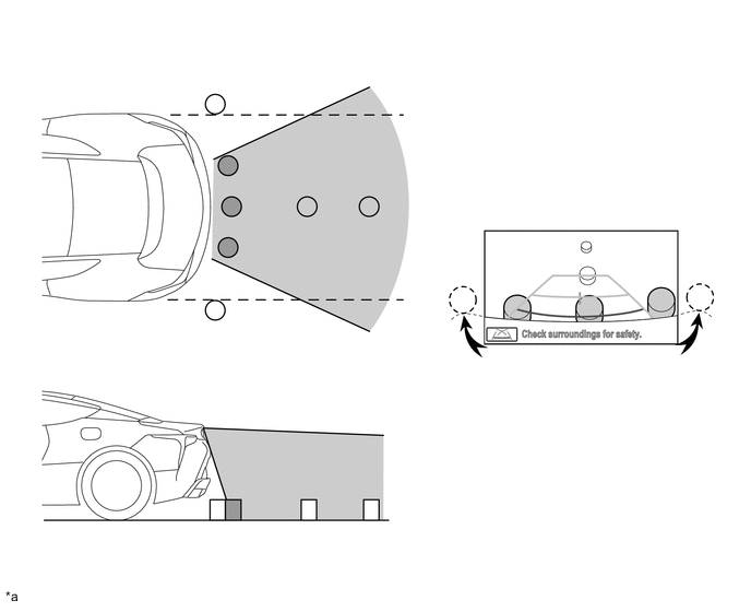
*a The illustration shown is an example only. The illustration may differ from the actual vehicle screen. - - Note
The area displayed on the screen may vary according to vehicle status or road conditions. The area covered by the television camera assembly is limited. The television camera assembly does not show objects close to either corner of the bumper or show the area under the bumper.
-
-
Warning Message
-
A warning message appears at the bottom of the screen under the following conditions. The warning message appears in the same language that has been selected by the language selector of the multi-display.
Messages Appearing at Bottom of Screen Warning Message Condition Check surroundings for safety. This message always appears during system operation.
-
-
Parking Guide Lines
-
The parking guide line can be selected from parking assist guide line display mode, distance guide line display mode and estimated course line display mode.
-
In each mode, fixed guide lines appear superimposed on a view of the area behind the vehicle. These guide lines can be used to assist the driver while backing up the vehicle.
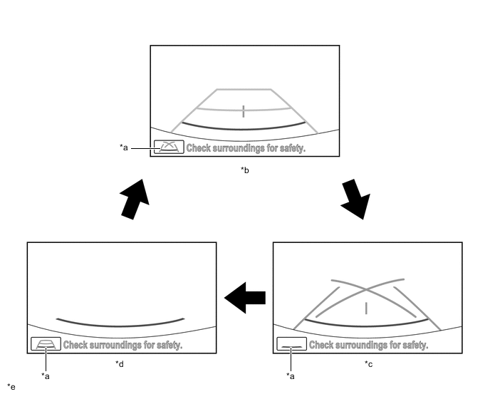
*a Display Mode Screen Button *b Estimated Course Line Display Mode *c Parking Assist Guide Line Display Mode *d Distance Guide Line Display Mode *e The illustration shown is an example only. The illustration may differ from the actual vehicle screen. - - -
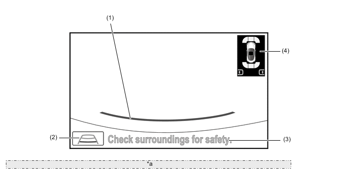
A description of the estimated course line display mode is provided in the following diagram.
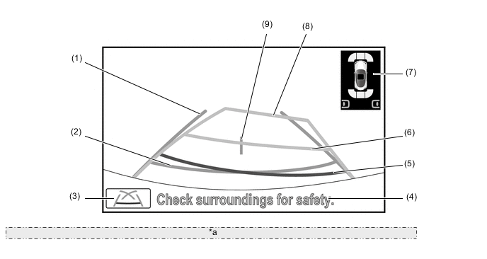
*a The illustration shown is an example only. The illustration may differ from the actual vehicle screen. Item Description (1) Vehicle Width Guide Line (Blue) Indicates the estimated vehicle width. (2) Distance Guide Line (Blue) Indicates a position on the ground approximately 0.5 m (1.6 ft.) behind the rear bumper. (3) Display Mode Screen Button Pressing this button changes the display mode. (4) Warning Message Display Area Area where warning message is displayed. (5) Distance Guide Line (Red) Moves together with estimated course lines in sync with the steering wheel. The center of the line indicates a position on the ground approximately 0.5 m (1.6 ft.) behind the rear bumper. (6) Distance Guide Line (Yellow) Moves together with estimated course lines in sync with the steering wheel. The center of the line indicates a position on the ground approximately 1.0 m (3.3 ft.) behind the rear bumper. (7) Lexus parking assist-sensor system Icon If an obstacle is detected when the Lexus parking assist-sensor system is activated, the approximate distance between the vehicle and the obstacle is displayed. RCTA Icon* Displays the detection direction superimposed on the screen when the RCTA function detects a vehicle approaching. (8) Estimated Course Line (Yellow) Moves in sync with the steering wheel to indicate the estimated reverse course of the vehicle. (9) Vehicle Center Guide Line (Blue) Indicates the estimated position on the ground of the center of the vehicle. *: Models with blind spot monitor system
-
A description of the parking assist guide line display mode is provided in the following diagram.
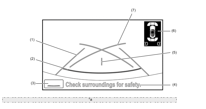
*a The illustration shown is an example only. The illustration may differ from the actual vehicle screen. Item Description (1) Vehicle Width Guide Line (Blue) Indicates the estimated vehicle width. (2) Distance Guide Line (Red) Indicates a position on the ground approximately 0.5 m (1.6 ft.) behind the rear bumper. (3) Display Mode Screen Button Pressing this button changes the display mode. (4) Warning Message Display Area Area where warning message is displayed. (5) Vehicle Center Guide Line (Blue) Indicates the estimated position on the ground of the center of the vehicle. (6) Lexus parking assist-sensor system Icon If an obstacle is detected when the Lexus parking assist-sensor system is activated, the approximate distance between the vehicle and the obstacle is displayed. RCTA Icon* Displays the detection direction superimposed on the screen when the RCTA function detects a vehicle approaching. (7) Parking Assist Guide Line (Blue) Indicates the path the vehicle will follow if the driver turns the steering wheel fully. *: Models with blind spot monitor system
-
A description of the distance guide line display mode is provided in the following diagram.
*a The illustration shown is an example only. The illustration may differ from the actual vehicle screen. Item Description (1) Distance Guide Line (Red) Indicates a position on the ground approximately 0.5 m (1.6 ft.) behind the rear bumper. (2) Display Mode Screen Button Pressing this button changes the display mode. (3) Warning Message Display Area Area where warning message is displayed. (4) Lexus parking assist-sensor system Icon If an obstacle is detected when the Lexus parking assist-sensor system is activated, the approximate distance between the vehicle and the obstacle is displayed. RCTA Icon* Displays the detection direction superimposed on the screen when the RCTA function detects a vehicle approaching. *: Models with blind spot monitor system
-
-
Estimated Course Line Display Mode of Parking Assist Monitor System
-
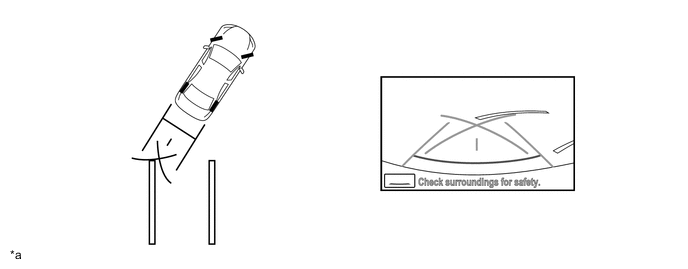
To use estimated course line display mode in perpendicular parking when parking the vehicle in a parking space, perform the following procedure:
-
Move the shift position to R.
-
Select estimated course line display mode.
-
An image appears on the display panel as illustrated below:
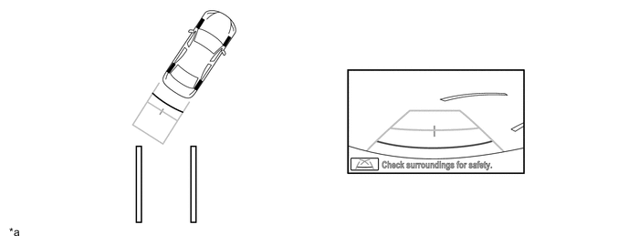
*a The illustration shown is example only. The illustration may differ from the actual vehicle screen. - - -
Turn the steering wheel so that the estimated course lines are within the parking space, and back up carefully.
*a The illustration shown is example only. The illustration may differ from the actual vehicle screen. - - -
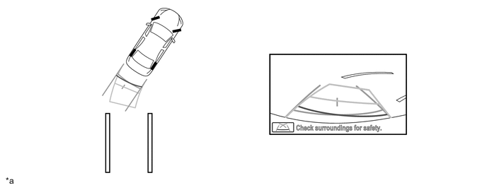
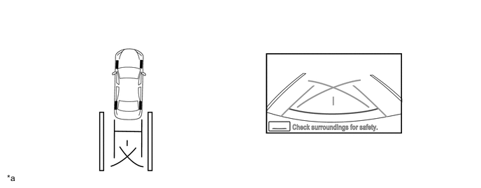
When the rear of the vehicle is within the parking space, turn the steering wheel in order to equalize the distance between the vehicle width guide lines and the parking space sidelines.
-
When the vehicle width guide lines and the parking space sidelines are parallel, straighten the steering wheel and then carefully back up until the entire vehicle is within the parking space.
*a The illustration shown is example only. The illustration may differ from the actual vehicle screen. - -
-
-
-
Parking Assist Guide Line Display Mode of Parking Assist Monitor System
-
To use parking assist guide line display mode in perpendicular parking when parking the vehicle in a parking space, perform the following procedure:
-
Move the shift position to R.
-
Select parking assist guide line display mode.
-
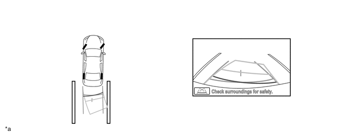
An image appears on the display panel as illustrated below:

*a The illustration shown is example only. The illustration may differ from the actual vehicle screen. - - -
Back the vehicle up and stop at the position in which the parking assist guide line comes in contact with the left side of the intended parking position.
*a The illustration shown is example only. The illustration may differ from the actual vehicle screen. - - -
Turn the steering wheel fully to the right and back the vehicle up.
-
Continue backing the vehicle up until the vehicle is parallel to the plotted lines.
-
Once the vehicle is parallel, aim the steering wheel straight ahead and back the vehicle up to the target stop position.
*a The illustration shown is example only. The illustration may differ from the actual vehicle screen. - -
-
-
-
-
DIAGNOSIS
-
The television camera assembly is equipped with a diagnosis function which can display a diagnosis menu for the parking assist monitor system. The method for entering the diagnosis menu screen is the same as the method used for the multi-display. For details, refer to the Repair Manual.
-