LEXUS PARKING ASSIST-SENSOR SYSTEM
-
FUNCTION OF MAIN COMPONENTS
Component Function Clearance Warning ECU Assembly
-
Judges the approximate distance between the vehicle and an obstacle based on signals from the ultrasonic sensors. Output signals are sent to the combination meter assembly, television camera assembly, headup display* and radio receiver assembly.
-
Sounds the No. 1 clearance warning buzzer.
Ultrasonic Sensors Detect the distance between the vehicle and an obstacle. No. 1 Clearance Warning Buzzer Sounds to inform the driver according to the distance to the obstacle. Combination Meter Assembly
-
Sends the on/off signal of the Lexus parking assist-sensor system to the clearance warning ECU assembly.
-
Receives obstacle detection signals and system malfunction signals from the clearance warning ECU assembly and displays the result on the multi-information display.
-
Illuminates the Lexus parking assist-sensor system indicator light when the Lexus parking assist-sensor system is turned on.
-
Sends the vehicle speed signal to the clearance warning ECU assembly.
Multi-display
-
Displays the location of an obstacle and the approximate distance between the vehicle and the obstacle.
-
Displays an indication of a malfunction or freezing of an ultrasonic sensor to inform the driver.
-
The sound volume, distance required to sound the No. 1 clearance warning buzzer and distance required to trigger the display can be chosen on the setup screen for the Lexus parking assist-sensor system.
Headup Display (Meter Mirror Sub-assembly)* Displays the location of an obstacle and the approximate distance between the vehicle and the obstacle. Television Camera Assembly
-
Captures images of the area behind the vehicle.
-
The Lexus parking assist-sensor system information is superimposed on the captured image. Then, the image is sent to the multi-display.
Radio Receiver Assembly Sends the setup signal for the Lexus parking assist-sensor system to the clearance warning ECU assembly. Steering Pad Switch Assembly Sends operation signals from switches to the combination meter assembly. ECM Sends the shift position signal to the clearance warning ECU assembly. Central Gateway ECU (Network Gateway ECU) Relays the signal between the CAN communication buses. DLC3
-
The Global TechStream (GTS) can be connected to read the Diagnostic Trouble Codes (DTCs) of malfunctions.
-
The Global TechStream (GTS) can be connected to change settings as desired by the user.
*: Models with headup display
-
-
OPERATING CONDITION
-
The operating condition of each sensor differs according to its installed position as shown in the table below:
Installation Position Operating Condition Front Corner
-
Engine switch is on (IG).
-
System is activated.
-
Shift position is other than P.
-
Vehicle speed is less than approximately 10 km/h (6 mph).*
Front Center
-
Engine switch is on (IG).
-
System is activated.
-
Shift position is other than P and R.
-
Vehicle speed is less than approximately 10 km/h (6 mph).
Rear Corner
-
Engine switch is on (IG).
-
System is activated.
-
Shift position is R.
Rear Center
-
Engine switch is on (IG).
-
System is activated.
-
Shift position is R.
Tech Tips
*: When the shift position is R, the system operates at any vehicle speed.
-
-
-
SYSTEM CONTROL
-
Detection Area
-
The detection areas of the ultrasonic sensor are as shown in the following illustration.
-
These detection areas are applicable when positioning a 400 mm (15.7 in.) diameter pole parallel or perpendicular to the ground. The ranges vary depending on the measuring method and type of obstacle.
Figure 1. Corner Area
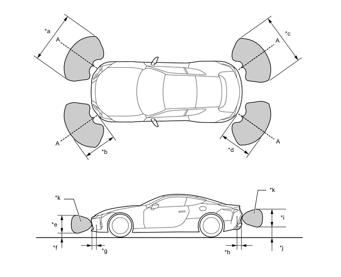
*a Approximately 1040 mm (40.9 in.) *b Approximately 600 mm (23.6 in.) *c Approximately 1040 mm (40.9 in.) *d Approximately 600 mm (23.6 in.) *e Approximately 660 mm (26.0 in.) *f Approximately 140 mm (5.51 in.) *g Approximately 200 mm (7.87 in.) *h Approximately 200 mm (7.87 in.) *i Approximately 660 mm (26.0 in.) *j Approximately 250 mm (9.84 in.) *k Ultrasonic Sensor Side View Detection Range Area - - 
Detection Area - - Note
The ultrasonic sensor side view detection range area (labeled *k) represents the cross section of the top view of the lines of detection range A. The area*k does not represent the entire side view detection range.
Figure 2. Center Area
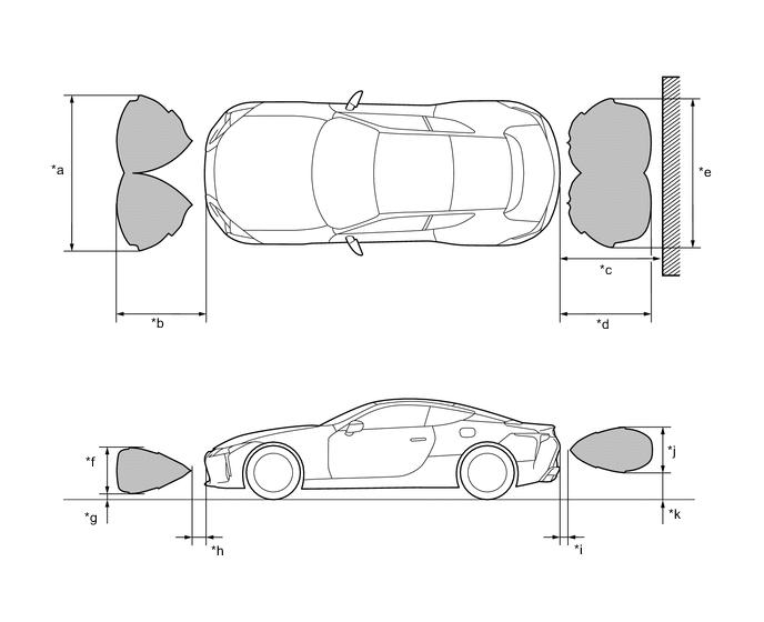
*a Approximately 1900 mm (74.8 in.) *b Approximately 900 mm (35.4 in.) *c Approximately 1500 mm (59.1 in.) *d Approximately 1200 mm (47.2 in.) *e Approximately 1700 mm (66.9 in.) *f Approximately 800 mm (31.5 in.) *g Approximately 70 mm (2.76 in.) *h Approximately 200 mm (7.87 in.) *i Approximately 200 mm (7.87 in.) *j Approximately 560 mm (22.0 in.) *k Approximately 200 mm (7.87 in.) - - Detection Area - -
-
-
-
DIAGNOSIS
-
If a system malfunction is detected, the clearance warning ECU assembly stores Diagnostic Trouble Codes (DTCs) in its memory. For details, refer to the Repair Manual.
-