BRAKE CONTROL SYSTEM
-
CONSTRUCTION
-
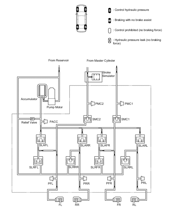
The brake actuator assembly is composed of switching solenoid valves (SMC1 and SMC2), an accumulator pressure sensor (PACC), master cylinder pressure sensors (PMC1 and PMC2), wheel cylinder pressure sensors (PFR, PFL, PRR and PRL) and linear solenoid valves (SLAFR, SLAFL, SLARL, SLARR, SLRFR, SLRFL, SLRRL and SLRRR).
Figure 1. Brake Actuator Assembly
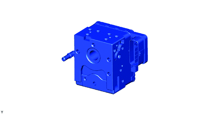
*1 Brake Master Cylinder Reservoir Assembly *2 Brake Master Cylinder Assembly *3 Accumulator *4 Pump Motor *5 Brake Stroke Simulator Cylinder Sub-assembly *6 Brake Actuator Assembly *7 Relief Valve *8 Accumulator Pressure Sensor *9 Master Cylinder Pressure Sensor (PMC2) *10 Master Cylinder Pressure Sensor (PMC1) *11 Switching Solenoid Valve (SMC2) *12 Switching Solenoid Valve (SMC1) *13 Linear Solenoid Valve (SLAFL) *14 Linear Solenoid Valve (SLARR) *15 Linear Solenoid Valve (SLAFR) *16 Linear Solenoid Valve (SLARL) *17 Linear Solenoid Valve (SLRFL) *18 Linear Solenoid Valve (SLRRR) *19 Linear Solenoid Valve (SLRFR) *20 Linear Solenoid Valve (SLRRL) *21 Wheel Cylinder Pressure Sensor (PFL) *22 Wheel Cylinder Pressure Sensor (PRR) *23 Wheel Cylinder Pressure Sensor (PFR) *24 Wheel Cylinder Pressure Sensor (PRL)
-
Switching Solenoid Valve
-
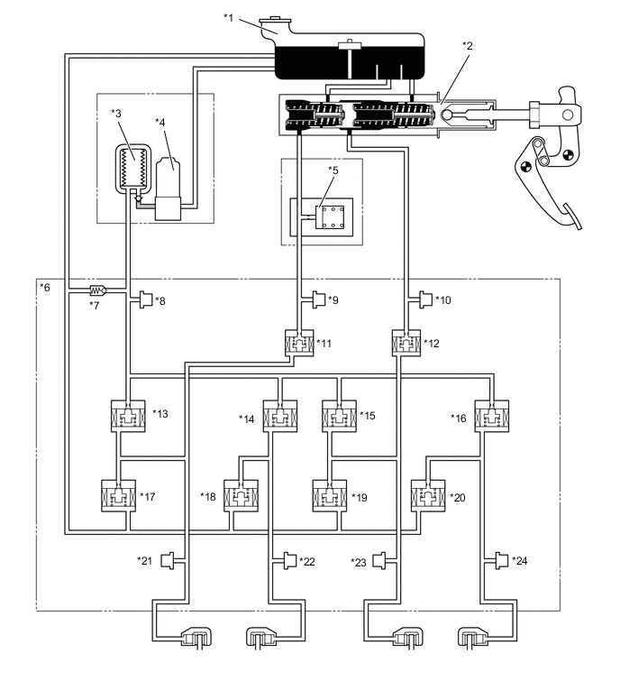
The valve opens and closes according to control signals from the skid control ECU to shut off the hydraulic path from the brake master cylinder assembly. The switching solenoid valves (SMC1 and SMC2) are installed to the hydraulic path between the brake master cylinder assembly and wheel cylinder.
Figure 2. SMC1 and SMC2

From Master Cylinder 
To Wheel Cylinder -
-
Linear Solenoid Valve
-
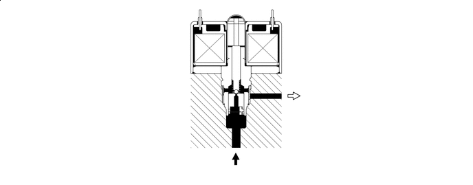
The valve opens and closes according to control signals from the skid control ECU to control the wheel cylinder hydraulic pressure. One pair of linear solenoid valves is installed to each wheel, for a total of four pairs. Each pair is composed of a pressure increase solenoid valve (SLA**) and pressure reduction solenoid valve (SLR**).
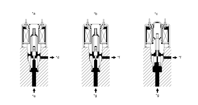
*a SLA** *b SLRF* *c SLRR* *d To Wheel Cylinder *e From Accumulator *f To Reservoir *g From Wheel Cylinder - - -
-
-
-
OPERATION
-
Normal System Operation
-
The SMC1 and SMC2 solenoid valves are closed and the hydraulic pressure circuit of each wheel cylinder is independent. As a result of this condition, SLA** and SLR** solenoid valve control is performed to increase, maintain or decrease the hydraulic pressure of each wheel.
Figure 3. 4 Wheels Braking with Control Hydraulic Pressure
-
-
Fail-safe System Operation
-
When a malfunction occurs that does not result in the system stopping, the following backup operations are performed to ensure braking force.
Figure 4. 4 Wheels Braking with Control Hydraulic Pressure (Minor Malfunction that Slightly Affects Braking)
Figure 5. 2 Diagonal Wheels Braking with Control Hydraulic Pressure + 1 Wheel Braking with No Brake Assist
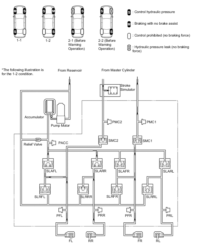
Figure 6. 3 Wheels Braking with Control Hydraulic Pressure
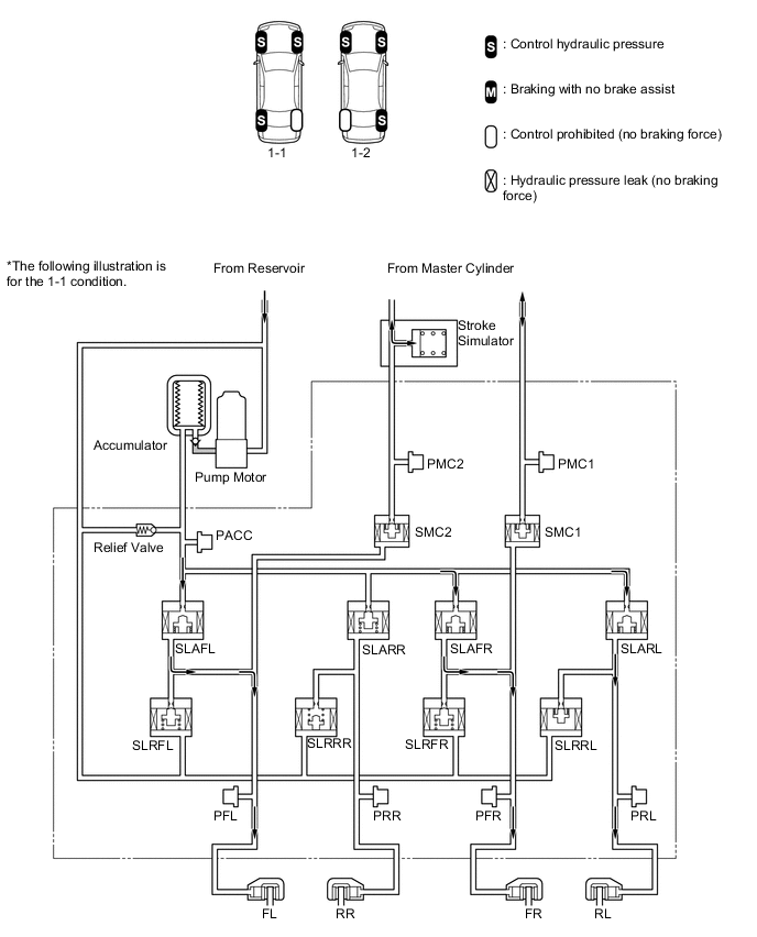
Figure 7. 1 Wheel Braking with No Brake Assist + 3 Wheels Braking with Control Hydraulic Pressure
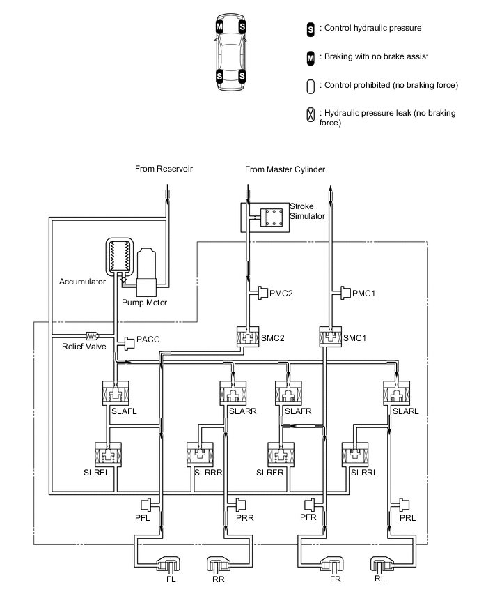
Figure 8. Front 2 Wheels Braking with No Brake Assist + Rear 2 Wheels Braking with Control Hydraulic Pressure
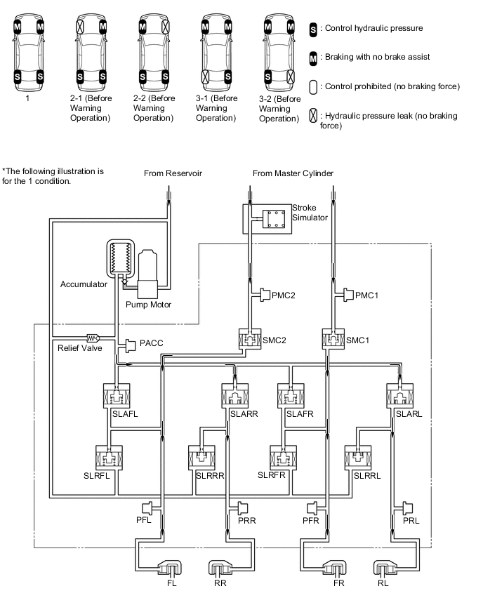
Figure 9. Front 2 Wheels Braking with No Brake Assist + Rear 1 Wheel Braking with Control Hydraulic Pressure

-
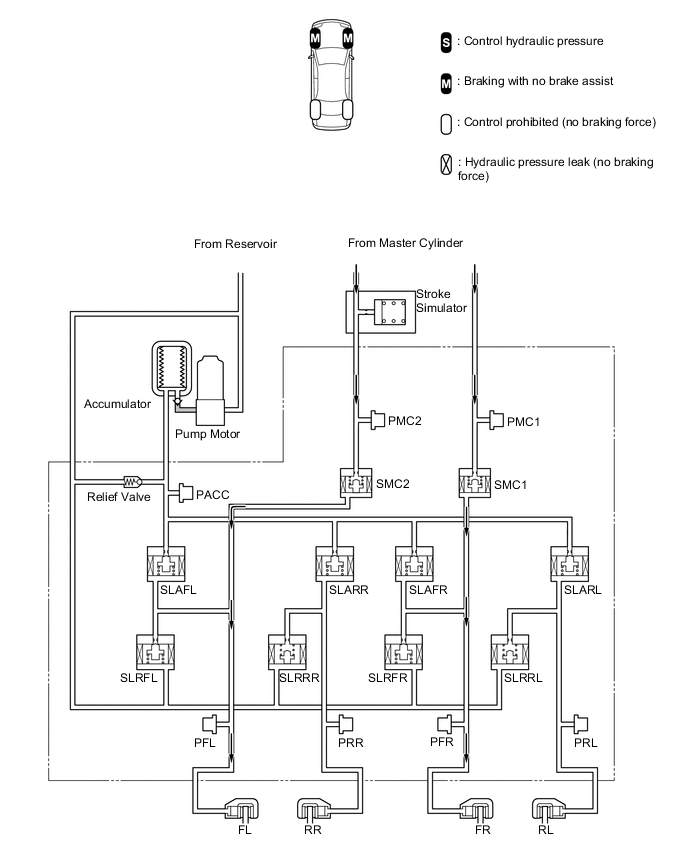
When the skid control ECU assembly system stops in response to a malfunction in the power source and power supply system (such as the pump motor and accumulator), braking is performed without brake assist for the front 2 wheels to ensure braking force.
Figure 10. Front 2 Wheels with No Brake Assist
-
-