FUEL SYSTEM
-
CONSTRUCTION
-
A fuel suction tube with pump and gauge assembly that has an integrated fuel filter, fuel pump (for low pressure) and fuel sender gauge assembly is used.
-
The fuel pump (for low pressure) is located in the fuel tank assembly. This pump pressurizes fuel to 400 kPa in order to send the fuel from the fuel tank assembly to the high and low pressure fuel systems.
-
A brushless motor is used for the fuel pump (for low pressure). Loss due to brush contact resistance is eliminated, reducing power consumption and achieving improved fuel economy.
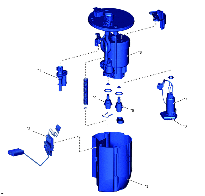
*1 Jet Pump *2 Fuel Sender Gauge Assembly *3 No. 1 Fuel Sub-tank *4 Fuel Main Valve Assembly *5 Fuel Pressure Regulator Assembly *6 Suction Filter *7 Fuel Pump *8 Fuel Filter Tech Tips
Conceptual Diagram of Structure:
-
Brushless Motor
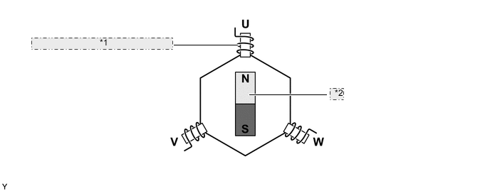
*1 Poles of Each Coil Switch in Order (Electronically Controlled) *2 Magnet Rotation -
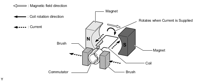
Motor with Brush
-
-