BODY STRUCTURE
-
CONSTRUCTION
-
Body Shell
-
The position of the body's structural parts is optimized, optimized connection methods are used and reinforcing materials are provided, creating a lightweight body structure with high rigidity and ensuring driving stability.
-
-
Cowl Side Outer
-
A cowl side outer (front body pillar gusset LWR (*3 in illustration)), which connects the front body pillar (such as the front body pillar extension upper outer (*1 in illustration)) and apron members (such as the front apron to cowl side member plate (*2 in illustration)), is installed to the front body pillars, ensuring superior steering response and roll feeling.
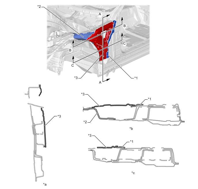
*1 Front Body Pillar Extension Upper Outer LH *2 Front Apron to Cowl Side Member Plate LH *3 Front Body Pillar Gusset LWR LH - - *a A - A Cross Section *b B - B Cross Section *c C - C Cross Section - -
-
-
Engine Compartment Brace
-
6 braces are optimally positioned inside the engine compartment to achieve high rigidity in the front body. As a result, superior driving stability is achieved.
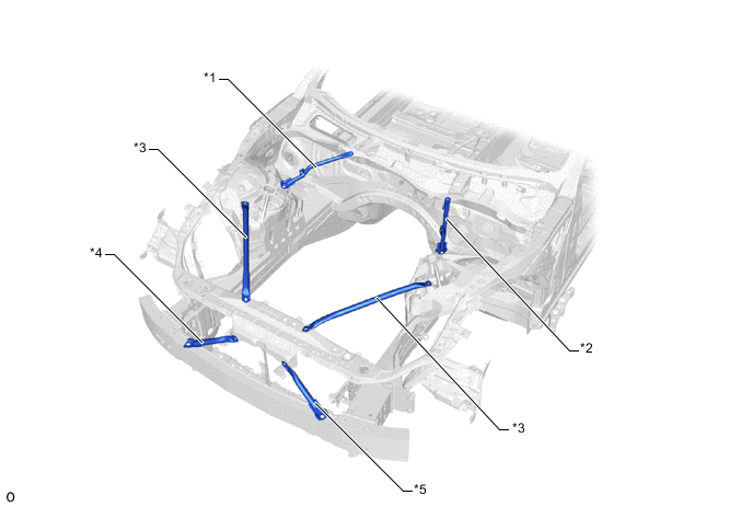
*1 Fender Apron Brace Sub-assembly RH *2 Fender Apron Brace Sub-assembly LH *3 Radiator Support Apron Brace RH *4 Lower Arm Bracket Brace Sub-assembly RH *5 Lower Arm Bracket Brace Sub-assembly LH - -
-
-
Suspension Tower
-
An aluminum die-cast*suspension tower (front spring support) is used to optimize the thickness and rib shape to achieve superior body rigidity and weight reduction.
Tech Tips
*: A method in which molten aluminum alloy, zinc alloy, etc. are forced into a mold cavity under high pressure to forge parts.
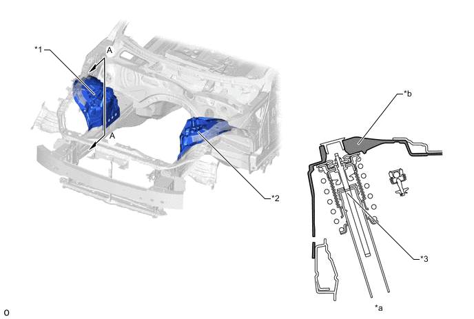
*1 Front Spring Support RH *2 Front Spring Support LH *3 Suspension - - *a A - A Cross Section *b Rib Shape Increases Rigidity of Suspension Installation Area
-
-
Cowl Top Side Stiffening Structure
-
The side welding range is expanded to remove the need for a service hole required by the conventional welding method. As a result, deformation in the cowl top side, caused by load input from the suspension, is suppressed to achieve high rigidity throughout the front body. As a result, superior driving stability is achieved.
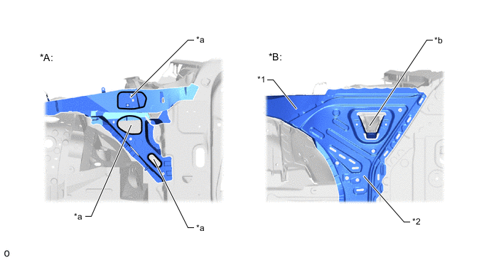
*A Conventional Welding Method *B LC *1 Cowl Top Side Panel LH *2 Front Body Pillar Gusset LWR LH *a Service Hole *b Drainage Hole
-
-
Cowl and Instrument Panel Reinforcement Ring Structure
-
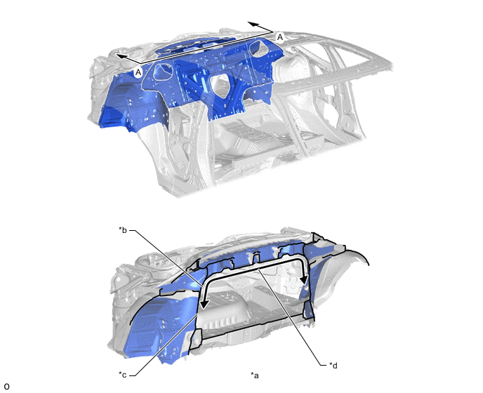
The cowl is given an underbody structure that connects the closed cross section of the cowl to the front body pillars and creates a ring structure for the cowl and instrument panel reinforcement assembly to achieve high rigidity for the cowl area. As a result, superior driving stability is achieved.
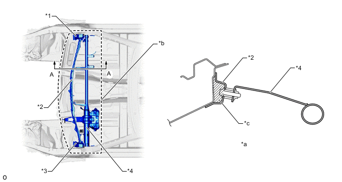
*1 Instrument Panel to Cowl Bracket No. 1 *2 Cowl Top Reinforcement Inner *3 Instrument Panel to Cowl Bracket No. 2 *4 Instrument Panel Reinforcement Assembly *a A - A Cross Section *b Ring Structure *c Closed Cross Section - -
-
-
Rocker
-
A large rocker cross section is provided to increase body rigidity, achieving superior driving stability.
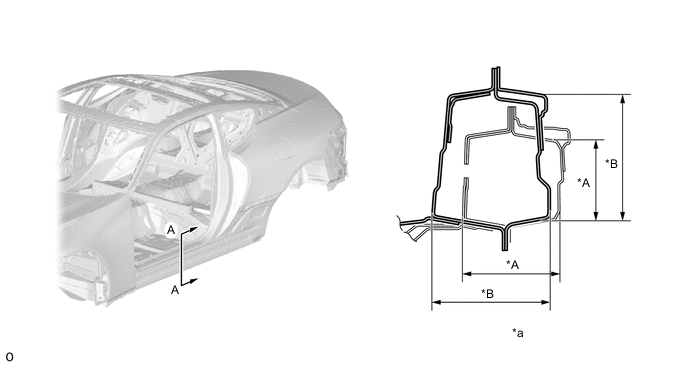
*A Conventional Model *B LC *a A - A Cross Section - -
-
-
Floor Cross Member Continuous Flange Structure
-
A continuous flange is used in the floor cross member frame connection area to increase the rigidity of the frame connection, achieving superior driving stability.
*A Conventional Model *B LC *1 Front Floor Cross Member RH *2 Front Floor Cross Member LH *3 Front Floor Cross Side Member RH *4 Front Floor Cross Side Member LH *a Floor Cross Member Frame Connection Area *b Cutout *c Continuous Flange - -
-
-
Large Floor Brace
-
A large brace (front floor brace sub-assembly center) is provided on the bottom of the floor to increase body rigidity, achieving superior driving stability.
*1 Front Floor Brace Sub-assembly Center - -
-
-
Rear Floor Cross Member
-
A rear floor cross member (rear floor cross member FR), which connects both sides of the rear wheel house, is provided to increase vehicle torsional rigidity, achieving superior driving stability.
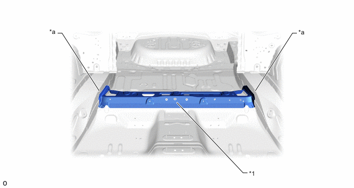
*1 Rear Floor Cross Member FR - - *a Rear Wheel House - -
-
-
Structural Adhesive, Laser Welding, Laser Screw Welding (LSW)
-
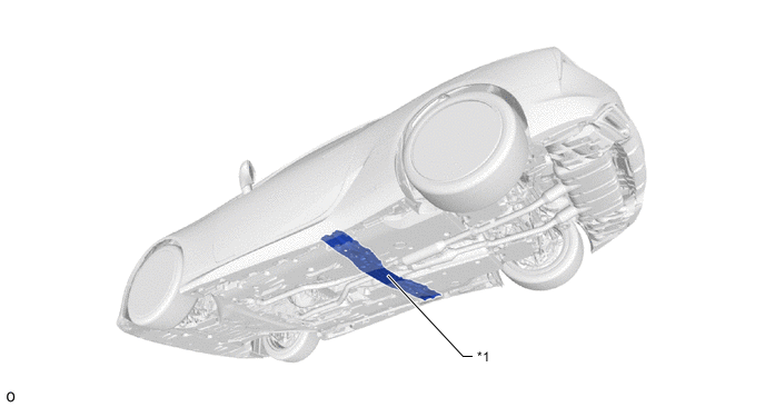
Structural adhesive*1, laser welding*2and Laser Screw Welding (LSW)*3are used over a large range to increase panel connecting rigidity, ensuring superior driving stability (steering response and feeling).
Tech Tips
*1: Compared to conventional spot welding where panels are only connected at certain points, this adhesive is used together with welds to connect body surfaces, minimizing bending and warping to maximize rigidity.
*2: This method increases panel connectivity in a line between spot welding points by using a connection method that uses a laser as a main heat source to concentrate light on the metal, melting and solidifying it in a localized area.
*3: Compared to conventional spot welding, this method reduces the pitch of welding points, allowing them to be concentrated in areas that need to be connected. Connections can be concentrated around frame openings to strengthen the structure of the vehicle.
Figure 1. Upper Body
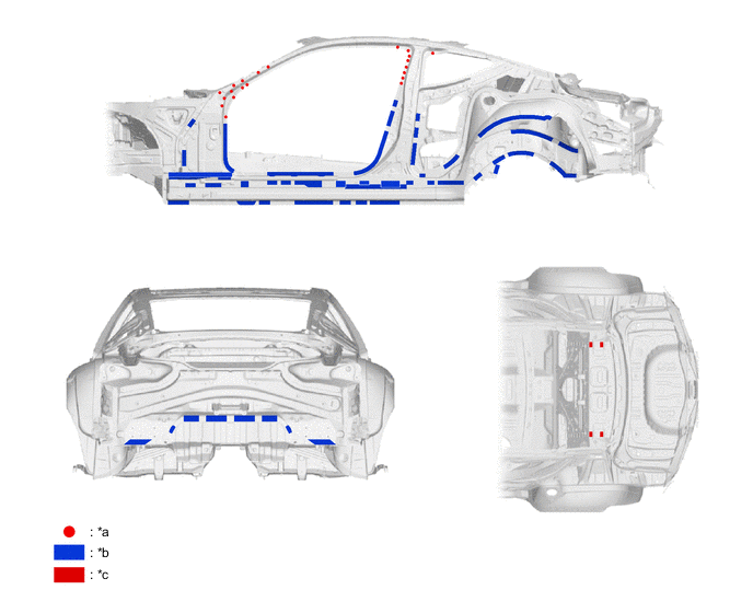
*a LSW *b Structural Adhesive *c Laser Welding - - Figure 2. Under Body
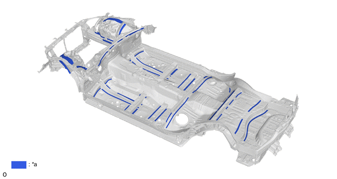
*a Structural Adhesive - -
-
-
Room Partition Panel
-
A room partition panel sub-assembly is installed in the upper back to ensure high rigidity, achieving superior steering response and roll feeling.
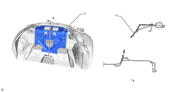
*1 Room Partition Panel Sub-assembly - - *a A - A Cross Section - -
-
-
Upper Back Ring Structure
-
The upper cross connects to the wheel houses in a ring structure to achieve high quality riding comfort and superior driving stability (steering response and feeling).
*a A - A Cross Section *b Upper Cross *c Rear Wheel House *d Ring Structure
-
-
Ultra High-tensile Strength Steel
-
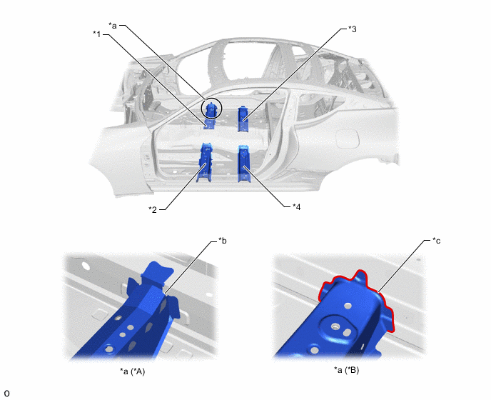
Ultra high-tensile strength steel (tensile strength: 980 MPa class) is used in the front body pillar reinforcement LWR (*1 in illustration) and center pillar upper hinge reinforcement (*5 in illustration) of the side member frame and ultra high-tensile strength steel (tensile strength: 1180 MPa class) is used in the front body pillar lower hinge retainer (*2 in illustration), fender panel inner (*3 in illustration) and roof panel reinforcement (*4 in illustration) to achieve a simplified lightweight structure while ensuring strength.
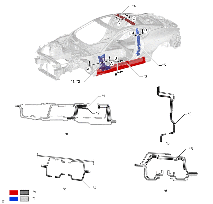
*1 Front Body Pillar Reinforcement LWR LH *2 Front Body Pillar Lower Hinge Retainer LH *3 Fender Panel Inner LH *4 Roof Panel Reinforcement *5 Center Pillar Upper Hinge Reinforcement No. 2 - - *a A - A Cross Section *b B - B Cross Section *c C - C Cross Section *d D - D Cross Section *e Ultra High-tensile Strength Steel
(Tensile Strength: 1180 MPa Class)
*f Ultra High-tensile Strength Steel
(Tensile Strength: 980 MPa Class)
-
-
CFRP Roof Panel
-
Depending on the grade, Carbon Fiber Reinforced Polymer (CFRP) is used in the roof panel to make it lightweight while ensuring the same level of rigidity as a steel roof to lower the center of gravity, achieving improved driveability by reducing the roll moment of inertia.
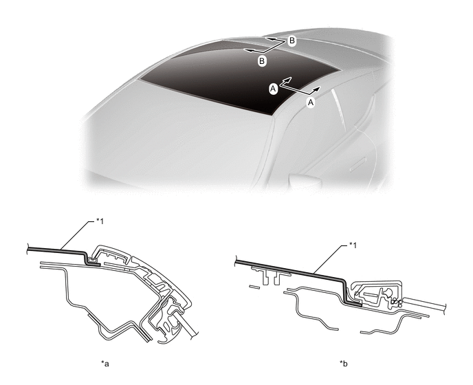
*1 Roof Panel - - *a A - A Cross Section *b B - B Cross Section 
CFRP - -
-
-
CFRP/G-SMC Luggage Compartment Door
-
Glass fiber-Sheet Molding Compound (G-SMC) is used in the luggage compartment door panel outer (*1 in illustration) and CFRP is used in the luggage compartment door panel inner (*2 in illustration) to achieve a simplified lightweight structure while ensuring the same level of strength and rigidity as a steel luggage compartment.
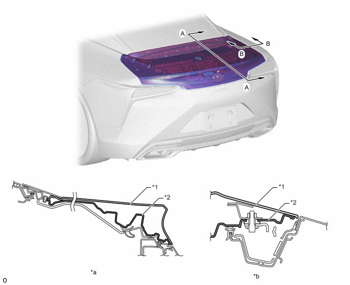
*1 Luggage Compartment Door Panel Outer *2 Luggage Compartment Door Panel Inner *a A - A Cross Section *b B - B Cross Section 
G-SMC CFRP
-
-
Side Member Outer Division
-
The side member outer is divided into separate parts to optimally position parts with a required sheet thickness, achieving weight reduction while ensuring superior rigidity.
-
The outer panel that runs from the front body pillar up to the roof rail is composed of the front body pillar reinforcement UPR (*2 in illustration) and roof side rail UPR (*1 in illustration), discontinuing the side outer panel to achieve weight reduction.
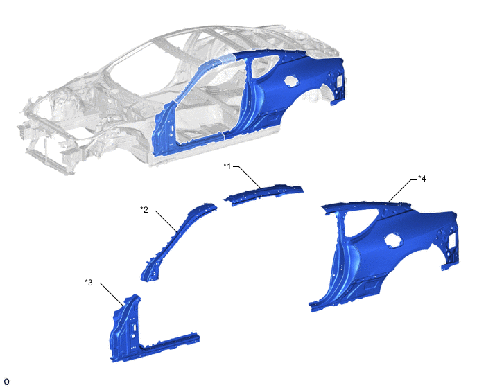
*1 Roof Side Rail UPR LH
(Sheet Thickness: 2.0 mm (0.08 in.))
*2 Front Body Pillar Reinforcement UPR LH
(Sheet Thickness: 2.0 mm (0.08 in.))
*3 Side Panel Outer No. 2 LH
(Sheet Thickness: 0.75 mm (0.03 in.))
*4 Front Side Panel Outer LH
(Sheet Thickness: 0.9 mm (0.04 in.))
-
-