ACTIVE REAR WING SYSTEM
-
OPERATION
-
The active rear wing assembly consists of a rear spoiler motor (*5 in illustration), link mechanism (*3 in illustration), wing (*2 in illustration) and base plate (*4 in illustration).
-
2 Hall ICs are built into the rear spoiler motor (*5 in illustration). Each Hall IC sends pulse signals to the spoiler control ECU assembly to provide feedback on the position of the active rear wing.
-
The active rear wing extends via the following operations.
-
The rear spoiler motor (*5 in illustration) rotates the spindle bolt (*c in illustration) to move the spindle nut (*d in illustration) vertically.
-
The vertical movement of the spindle nut (*d in illustration) is converted into the rotational movement of the arms (*f in illustration) through the nut guide (*e in illustration) to rotate the arms at the center of the rod sub-assembly (*g in illustration), rotating the rod sub-assembly (*h in illustration).
-
The rotational movement of the rod sub-assembly (*h in illustration) is connected to the link mechanisms (*3 in illustration) to raise and retract the active rear wing. The link angle is restricted by stoppers, and after the stoppers are contacted, the rod sub-assembly (*h in illustration) is tightened to a specified angle to ensure wing rigidity.
-
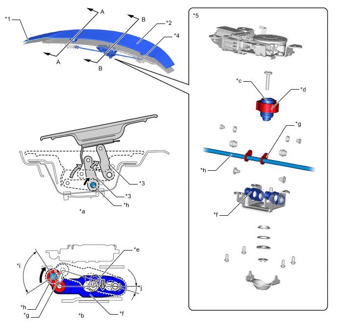
*1 Active Rear Wing Assembly *2 Wing (Spoiler Sub-assembly RR) *3 Link Mechanism *4 Base Plate *5 Rear Spoiler Motor - - *a A - A Cross Section *b B - B Cross Section *c Spindle Bolt *d Spindle Nut *e Nut Guide *f Arm *g Rod Sub-assembly Center Arm *h Rod Sub-assembly *i Rod Sub-assembly Operation Range *j Arm Operation Range 
Rod Sub-assembly Rotation Direction (when Raising) 
Rod Sub-assembly Center Arm Operation Direction (when Raising) 
Nut Guide Operation Direction (when Raising) 
Link Sub-assembly Operation Direction (when Raising) -