HEADUP DISPLAY SYSTEM
-
FUNCTION OF MAIN COMPONENTS
Component Function Headup Display (Meter Mirror Sub-assembly)
-
Meter Mirror ECU
Receives signals from ECUs and switches and projects vehicle information onto the windshield glass. No. 3 Combination Switch Assembly
-
HUD Main Switch
Outputs the HUD main switch on signal to the headup display. Combination Meter Assembly
-
Sends information display and master warning display request signals to the headup display.
-
Sends each type of setting signal to the headup display.
Hybrid Vehicle Control ECU Assembly
-
Sends the hybrid system output, regeneration status and drive mode signals to the headup display.
-
Sends warning display and information display request signals from the dynamic radar cruise control system to the headup display.*1
ECM Sends engine speed signals to the headup display. Driving Support ECU Assembly*1 Sends warning display and information display request signals from the pre-collision system to the headup display. Forward Recognition Camera*1 Sends warning display and information display request signals from the Lane Departure Alert (LDA) system*2, Lane Keeping Assist (LKA) system*3 or road sign assist system*4 to the headup display. Millimeter Wave Radar Sensor Assembly*1 Radiates millimeter radar waves forward, uses the reflected waves to detect the presence of a vehicle ahead, the vehicle-to-vehicle distance and the relative speed and direction of the vehicle ahead, and then transmits this information to the driving support ECU assembly. Shift Control ECU Sends shift position signals to the headup display. Skid Control ECU Assembly Sends vehicle speed signals to the headup display. Radio Receiver Assembly
-
Sends the audio operation feedback display and telephone popup display request signals to the headup display.
-
Reroutes signals received from the navigation ECU to the headup display.
Navigation ECU*5 Sends the navigation system-linked display and compass display request signals to the radio receiver assembly. Main Body ECU (Multiplex Network Body ECU) Sends the taillight on signal to the headup display. Clearance Warning ECU Assembly Sends clearance sonar detection request signals to the headup display. Central Gateway ECU (Network Gateway ECU) Relays the signal between the CAN communication lines. DLC3 The Global TechStream (GTS) can be connected to read the Diagnostic Trouble Codes (DTCs) of malfunctions. *1: Models with Lexus Safety System+
*2: Models with LDA system
*3: Models with LKA system
*4: Models with road sign assist system
*5: Models with navigation system
-
-
SYSTEM CONTROL
-
When the meter mirror ECU inputs HUD main switch operation signals, it operates the display on the windshield glass.
-
The combination meter assembly sends each signal to the meter mirror ECU. Also, when audio-related operations are performed, the radio receiver assembly sends the current condition to the meter mirror ECU. The meter mirror ECU projects each image onto the windshield glass according to received signals.
-
The meter mirror ECU switches the brightness of the light source used for backlight illumination according to the status of the built-in brightness control sensor and headlight on/off signals.
-
-
FUNCTION
-
Display Function
-
When the HUD main switch is turned on after the power switch is turned on (IG), this function operates the display on the windshield glass.
-
If the power switch is turned off while the headup display is displayed, when the power switch is turned back on (IG), the display function resumes operation in the same condition it was in before the power switch was turned off.
-
The display position of the headup display is memorized in the electrical key transmitter sub-assembly carried by the driver when the power switch is turned off. When the power switch is turned back on (IG), the headup display position is restored.
-
-
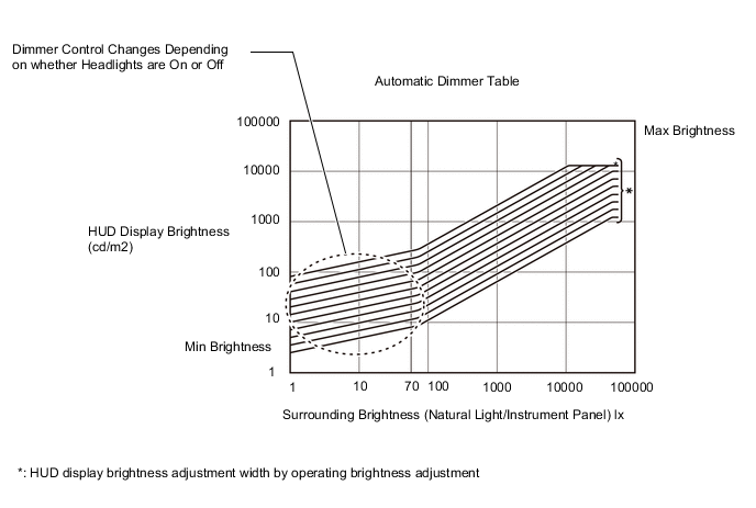
Automatic Brightness Adjustment Function
-
The brightness of the headup display automatically switches to a brightness appropriate for any situation (such as when the display brightness is adjusted by operating the brightness adjustment switch) according to the surrounding brightness detected by the built-in brightness control sensor.
-
When the surrounding brightness is darker than 70 lx (dusk), dimmer control changes depending on whether the headlights are on or off.
-
-
Manual Brightness Adjustment Function
-
The brightness of the headup display can be adjusted by operating the combination meter assembly display with the steering pad switches.
Brightness Adjustment Specification Item Specification Dimming amount per step 12.5% ←→ 17.6% ←→ 25% ←→ 35.3% ←→ 50% ←→ 70.5% ←→ 100% ←→ 141% ←→ 200% ←→ 282% ←→ 400% Operation method On for less than 0.5 seconds When pressed 1 time, dims up/down 1 step. On for 0.5 seconds or more When pressed and held, dims up/down 1 step every 0.24 seconds. 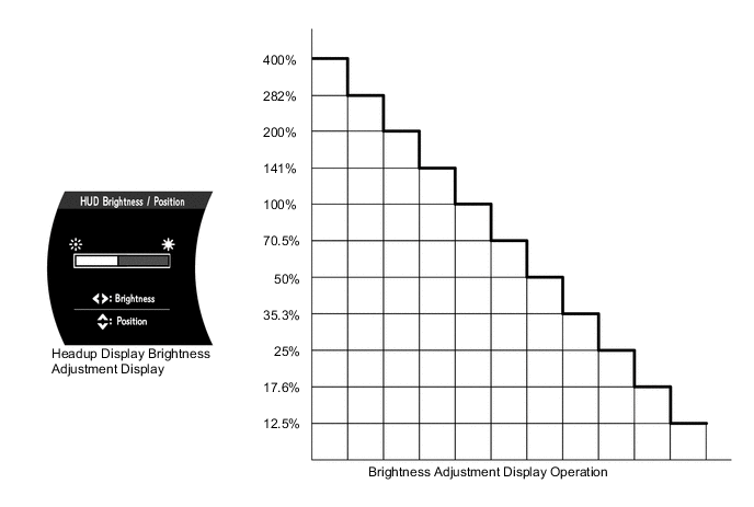
-
-
Display Position Adjustment Function
-
The position of the headup display can be vertically adjusted by operating the combination meter assembly display with the steering pad switches.
-
-
Displayed Item Customization Function
-
The following displayed items can be selected by changing the setting of the combination meter assembly.
-
Tachometer Settings (Tachometer/Hybrid System/Blank)
-
Navigation (ON/OFF)*
-
Driving Support (ON/OFF)
-
Compass (ON/OFF)*
-
Audio (ON/OFF)
-
HUD Rotation (Counterclockwise/Clockwise)
-
*: Models with navigation system
-
-
-