AIR CONDITIONING SYSTEM
-
FUNCTION OF MAIN COMPONENTS
-
The air conditioning system consists of the following parts:
Component Function Air Conditioning Pressure Sensor Detects the refrigerant pressure and sends the data to the air conditioning amplifier assembly. Air conditioning Amplifier Assembly Transmits and receives data to and from the switches and sensors, and controls the air conditioning system. Ambient Temperature Sensor (Thermistor Assembly) Detects the ambient temperature and outputs it to the air conditioning amplifier assembly. Battery ECU Assembly Sends the A/C ventilation request signal to the air conditioning amplifier assembly. Blower Motor with Fan Sub-assembly Driven according to the target airflow volume calculated by the air conditioning amplifier assembly to blow air toward the cabin and circulate the air inside the cabin. Central Gateway ECU (Network Gateway ECU) Relays the signal between the CAN communication lines. Combination Meter Assembly Sends the vehicle speed signal to the air conditioning amplifier assembly. DLC3 The Global TechStream (GTS) can be connected to read the Diagnostic Trouble Codes (DTCs) of malfunctions. Drive Mode Select (Combination Switch Assembly) Comf/Eco Mode Switch Sends the Eco switch operation signal to the air conditioning amplifier assembly. ECM Receives the signals from the engine coolant temperature sensor and transmits them to the air conditioning amplifier assembly. Evaporator Fin Sensor (No. 1 Cooler Thermistor) Detects the temperature of the cool air past the cooler evaporator sub-assembly and transmits the data to the air conditioning amplifier assembly. Glass Humidity Sensor (Rain Sensor) Detects the glass temperature, glass surroundings temperature and glass humidity, and outputs them to the air conditioning amplifier assembly. Heater Water Pump (Heater Accessory Assembly) Controlled by the No. 1 semiconductor power integration ECU in accordance with signals from the air conditioning amplifier assembly. Hybrid Vehicle Control ECU Assembly
-
Sends forced recirculation command signals to the air conditioning amplifier assembly.
-
Receives compressor operation signals and controls the motor with compressor assembly.
Integration Control and Panel Assembly Allows operation and adjustment of the air conditioning via switches. Main Body ECU (Multiplex Network Body ECU)
-
Sends solar energy level difference, glass temperature, glass surroundings temperature and glass humidity signals to the air conditioning amplifier assembly.
-
Receives heater water pump operation request signals and sends operation signals to the No. 1 semiconductor power integration ECU.
-
Receives PTC heater request signals and sends operation signals to the No. 2 semiconductor power integration ECU.
Compressor with Motor Assembly Performs suction, compression and discharge of refrigerant gas. Multi-display Displays the settings screen. No. 1 Air Conditioning Radiator Damper Servo Sub-assembly Damper Servo (for Driver Side Lower Layer Air Mix Door) Controlled by the air conditioning amplifier assembly to move the driver seat air mix control damper and adjust the driver side outlet air temperature. Damper Servo (for Driver Side Upper Layer Air Mix Door) No. 2 Air Conditioning Radiator Damper Servo Sub-assembly Damper Servo (for Passenger Side Lower Layer Air Mix Door) Controlled by the air conditioning amplifier assembly to move the front passenger seat air mix control damper and adjust the front passenger side outlet air temperature. Damper Servo (for Passenger Side Lower Layer Air Mix Door) No. 3 Air Conditioning Radiator Damper Servo Sub-assembly Damper Servo (for FACE/DEF Door) Controlled by the air conditioning amplifier assembly to move the mode control damper and switch the registers. Damper Servo (for FOOT Door) No. 4 Air Conditioning Radiator Damper Servo Sub-assembly (for DEF Door) No. 1 Blower Damper Servo Sub-assembly (for Fresh/Recirculation Damper) Driven by the air conditioning amplifier assembly to move the fresh/recirculation damper. No. 1 Semiconductor Power Integration ECU Operates the heater water pump according to heater water pump operation request signals received from the main body ECU (multiplex network body ECU). No. 2 Semiconductor Power Integration ECU*1 Operates the PTC heater according to PTC heater operation request signals received from the main body ECU (multiplex network body ECU). PTC Heater (Quick Heater Assembly)*1 Consists of a Positive Temperature Coefficient (PTC) element, an aluminum fin and a brass plate. Power Steering ECU Sends the loading control level signal to the air conditioning amplifier assembly. Radio Receiver Assembly Sends function customization information from the multi-display setting screen to the air conditioning amplifier assembly. Cooler Thermistor (Room Temperature Sensor) Detects the internal temperature inside the cabin and outputs that data to the air conditioning amplifier assembly. Smog Ventilation Sensor*2 Detects harmful elements (CO, HC, NOx) and outputs it to the air conditioning amplifier assembly. Solar Sensor (Automatic Light Control Sensor) Detects the changes in the amount of solar energy and outputs them to the air conditioning amplifier assembly via the main body ECU (multiplex network body ECU). *1: Models with PTC heater
*2: Models with automatic recirculation control
-
-
-
SYSTEM CONTROL
-
Control List
Control Function Neural Network Control This control is capable of performing complex control by artificially simulating the information processing method of the nervous system of living organisms in order to establish a complex input/output relationship that is similar to a human brain. Pollen Removal Mode Control Sends air which has passed through the air refiner element to the area around the upper part of the bodies of the passenger. This air has been filtered by the air refiner element in order to remove pollen. Lexus Climate Concierge Control When the air conditioning system, seat heater system*1, climate control seat system and steering wheel heater system*2 are controlled in auto mode, the air conditioning amplifier assembly automatically controls the air conditioning system, seat heater system*1, climate control seat blower unit and steering wheel heater system*2. When the air conditioning system performs heater mode control, the air conditioning amplifier assembly operates the seat heater system*1 and steering wheel heater system*2. When the air conditioning system performs cooler mode control, the air conditioning amplifier assembly operates the climate control seat system. Outlet Air Temperature Control Based on the temperature set by the temperature control switch, the neural network control calculates the outlet air temperature based on the input signals from various sensors. The temperature setting for the driver and front passenger is controlled independently in order to provide a separate vehicle interior temperature for the right and left sides of the vehicle. Thus, air conditioning control that accommodates occupant preferences has been achieved. Automatic Recirculation Control*3 Automatically changes the air inlet mode to fresh air or recirculate mode in accordance with the level of harmful elements in the outside air, cabin temperature and outside temperature. Changes the sensitivity of the smog ventilation sensor. Blower Control Controls the blower motor in accordance with the airflow volume that has been calculated by neural network control based on the input signals from various sensors. Automatically increases the blower level when the defroster is on. Air Outlet Control Automatically switches the air outlets in accordance with the outlet mode that has been calculated by neural network control based on the input signals from various sensors. In accordance with the engine coolant temperature, outside air temperature, amount of sunlight, required blower, outlet temperature and vehicle speed conditions, this control automatically switches the blower outlet to FOOT/DEF mode to prevent the windows from becoming fogged when the outside air temperature is low. Odor Suppression Control When the air conditioning system is started, the compressor with motor assembly is operated with the blower off for approximately 6 seconds to cool the No. 1 cooler evaporator assembly. As a result, the odor inside the air conditioning unit is adsorbed in the water that forms on the surface of the evaporator. From approximately 6 to 11 seconds after the system is started, the air outlet mode is set to FOOT mode and the blower operates at low speeds to discharge the air inside the air conditioning unit into the footwell. From approximately 11 to 17 seconds after the system is started, the system returns to the previously set control mode. These controls prevent the air inside the air conditioning unit from blowing out toward the face area when the air conditioning system is started, reducing feelings of discomfort. Charge/Discharge Balance Management Load Control
-
When there is an insufficient charge due to the excessive use of electrical equipment or driving in traffic jams for a long period of time, or when the auxiliary battery is excessively discharged due to the extended use of electrical equipment with the engine off, the air conditioning amplifier assembly reduces the power consumption of the air conditioning system to ensure a stable supply of power to the 12 V vehicle system. Furthermore, when charge/discharge balance management load control is performed, "High Power Consumption Partial Limit On AC/Heater Operation" is displayed on the multi-information display in the combination meter assembly.
-
The air conditioning amplifier assembly inputs sub-battery voltage condition signals from the ECM and performs charge/discharge balance management load control according to the voltage condition.
-
Charge/discharge balance management load control is canceled when the power switch is turned off or the voltage condition returns to normal.
Air Inlet Control Automatically controls the air inlet control damper to achieve the calculated outlet air temperature that is required. Drives the No. 1 blower damper servo sub-assembly (fresh/recirculation damper) in accordance with the operation of the air inlet control switch and moves the dampers to the FRESH or RECIRC position. Compressor Control The air conditioning amplifier assembly calculates the target speed of the compressor based on the target evaporator temperature (which is calculated by the room temperature sensor, ambient temperature sensor and solar sensor) and the actual evaporator temperature that is detected by the evaporator temperature sensor in order to control the compressor speed. The air conditioning amplifier assembly calculates the target evaporator temperature, which includes corrections based on the vehicle interior humidity (which is obtained from the humidity sensor) and the windshield glass inner surface humidity (which is calculated by the humidity sensor, solar sensor, room temperature sensor, mode damper position, and wiper operation condition). Accordingly, the air conditioning amplifier assembly controls the compressor speed to an extent that would not inhibit the proper cooling performance or defogging performance. Turns the air conditioning on automatically when the AUTO button is pressed when the blower is on and the air conditioning is off. Decreases the compressor speed in order to ensure quietness when the vehicle is stopped or the engine is off. PTC Heater Control*4 When the power switch is turned on (IG) and the blower motor is turned on, the air conditioning amplifier assembly turns on the PTC heater (quick heater assembly) if the following conditions are met.
-
Engine coolant temperature is below the specified temperature.
-
Ambient temperature is below the specified temperature.
-
Tentative air mix damper opening angle is above the specified value (MAX HOT).
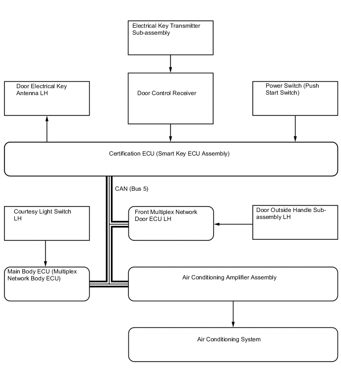
Memory Call Control Memorizes the last air conditioning settings when the power switch is turned from on (IG) to off in accordance with the ID code of the electrical key transmitter sub-assembly that is used to operate the vehicle. Memory call control then recalls the settings if the electrical key transmitter sub-assembly is used when the power switch is turned on (IG). This function operates when both of the following conditions are met:
-
The driver door is unlocked by an entry unlock operation or wireless unlock operation, and then the driver door is opened.
-
Power switch is turned on (IG).
ECO Drive Mode Control When set to ECO drive mode, the air conditioning amplifier assembly decreases the blower speed and switches to air inlet mode. Blower Customization Control*5 The air volume can be adjusted to 3 levels using the FAST ECO switch on multi-display: NORMAL-ECO (small air volume)-FAST (large air volume) Diagnosis A Diagnostic Trouble Code (DTC) is stored in memory when the air conditioning amplifier assembly detects a problem with the air conditioning system. *1: Models with seat heater system
*2: Models with steering wheel heater system
*3: Models with automatic recirculation control
*4: Models with PTC heater
*5: Models with blower customization control
-
-
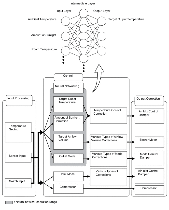
Neural Network Control
-
In the previous automatic air conditioning system, the air conditioning amplifier assembly determined the required outlet air temperature and blower air volume in accordance with a calculation formula that had been obtained based on information received from the sensors. However, because the senses of a person are rather complex, a given temperature is sensed differently, depending on the environment in which the person is situated. For example, a given amount of solar radiation can feel comfortably warm in a cold climate, but extremely uncomfortable in a hot climate. Therefore, as a technique for performing a high level of control, a neural network is used in the automatic air conditioning system. With this technique, the data that has been collected under varying environmental conditions is stored in the air conditioning amplifier assembly, which effects control to provide enhanced air conditioning comfort.
-
The neural network control consists of neurons in an input layer, an intermediate layer, and an output layer. The input layer neurons process the input data of the ambient temperature, the amount of sunlight and the room temperature based on the outputs of the switches and sensors, and output them to the intermediate layer neurons. Based on this data, the intermediate layer neurons adjust the strength of the links among the neurons. The sum of this data is then calculated by the output layer neurons in the form of the required outlet temperature, solar correction, target airflow volume and outlet mode control volume. Accordingly, the air conditioning amplifier assembly controls the servo motors and blower motor with fan sub-assembly in accordance with the control volumes that have been calculated by the neural network control.
-
-
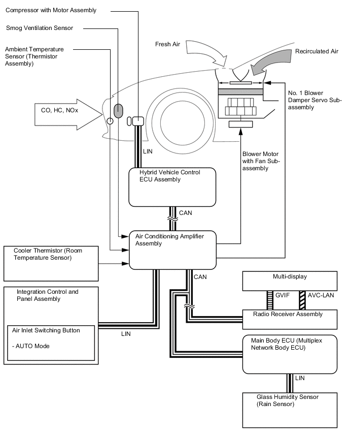
Automatic Recirculation Control (Models with Automatic Recirculation Control )
-
When automatic recirculation control is operating, the air conditioning amplifier assembly automatically changes air inlet mode to fresh air or recirculate air mode based on signals from the smog ventilation sensor, ambient temperature sensor (thermistor assembly), cooler thermistor (room temperature sensor) and glass humidity sensor (rain sensor) when AUTO air inlet mode is selected.
-
The air conditioning amplifier assembly detects harmful elements (CO, HC and NOx) based on smog ventilation sensor signals and automatically switches air inlet mode to recirculate air mode to prevent such harmful elements from entering the cabin.
-
The air conditioning amplifier assembly detects the room temperature based on a cooler thermistor (room temperature sensor) signal and automatically switches air inlet mode to recirculate air mode to prevent the room temperature from becoming too high.
-
The air conditioning amplifier assembly detects the outside temperature and room humidity based on a ambient temperature sensor (thermistor assembly) and glass humidity sensor (rain sensor) signal and automatically switches air inlet mode to fresh air mode to prevent the windshield from fogging up.
Tech Tips
The smog ventilation sensor cannot detect elements such as smoke from a bonfire or factory exhaust, foul or animal odors, and dirt or dust particles. Therefore, air inlet mode is not switched in accordance with those elements. Depending on the direction of the wind, the smog ventilation sensor might not be able to detect the undesirable elements (CO, HC and NOx), allowing them to enter the cabin.
-
-
-
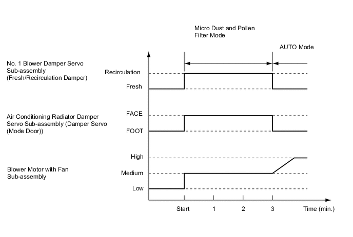
Pollen Removal Mode Control
-
When the pollen removal mode switch on the multi-display assembly is operated, the pollen removal mode control is activated. The air vent is switched to the FACE mode and recirculated pollen-free air flows around the upper body areas of the driver and front passenger.
-
When the pollen removal mode switch signal is received by the air conditioning amplifier assembly, the air conditioning amplifier assembly controls the No. 1 blower damper servo sub-assembly, No. 1 air conditioning radiator damper servo sub-assembly and blower motor with fan sub-assembly as shown in the timing chart below.
-
This control usually operates for approximately 3 minutes. However, when the outside temperature is low, the control will operate for approximately 1 minute.
-
After this control stops operating, the air conditioning amplifier assembly controls the air conditioning system using AUTO mode.
Figure 1. Timing Chart (Sample)
-
-
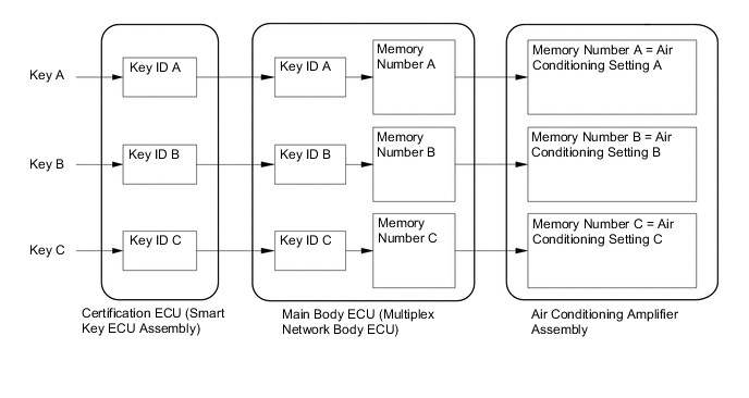
Memory Call Control
-
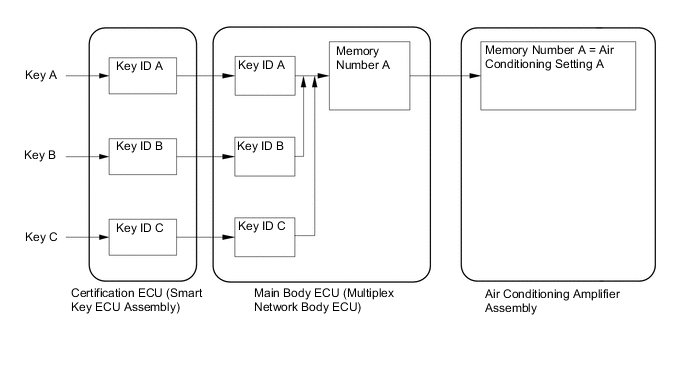
The air conditioning amplifier assembly stores the air conditioning settings for each memory number when the power switch is turned off.
-
The main body ECU (multiplex network body ECU) converts the key ID code into a memory number, stores it and sends the converted signal to the air conditioning amplifier assembly.
-
The air conditioning amplifier assembly stores the memory number and air conditioning settings.
-
When the doors are unlocked, the certification ECU (smart key ECU assembly) recognizes the key ID code and sends it to the main body ECU (multiplex network body ECU).
-
Upon receiving the key ID code signal, the main body ECU (multiplex network body ECU) converts the signal into a memory number signal and sends it to the air conditioning amplifier assembly.
-
Then the air conditioning amplifier assembly recalls the stored air conditioning settings based on the memory number signal when the power switch is turned on (IG).
-
The following air conditioning system settings can be memorized:
Setting Condition Air Conditioning Switch On or Off Dual Switch On or Off AUTO Switch On or Off ECO Switch On or Off Temperature Setting Driver LO, 16°C to 32°C (65°F to 85°F) or HI Front Passenger LO, 16°C to 32°C (65°F to 85°F) or HI Blower Fan Speed Level 1 to 7 (Manual Control Mode) Air Inlet Mode Fresh or Recirculate Air Outlet Mode Face, Bi-level, Foot, Foot and Defroster or Defroster Tech Tips
-
Memory call control of the air conditioning system can be canceled or re-enabled using Global TechStream (GTS).
-
The main body ECU (multiplex network body ECU) can store a maximum of 3 memory numbers.
-
The memory call function recalls the key ID that was recognized when the door was unlocked. This happens even when the user brings 2 keys or more, or the user uses different keys to unlock the door and to turn the power switch on (IG).
-
Using the Global TechStream (GTS), the main body ECU (multiplex network body ECU) can be made to convert the ID numbers of different keys to a desired memory number. Therefore, all key IDs can be converted to an identical memory number, or 2 memory numbers can be divided among 3 keys.
-
For details about key ID code registration, refer to the Repair Manual.
-
-
-
ECO Drive Mode Control
-
During ECO drive mode, the air conditioning amplifier assembly restricts the air conditioning system performance under specified conditions, thus improving fuel economy.
-
The ECO drive mode control is activated when the integration control and panel assembly (drive mode select) is operated, and then restricts the air conditioning system performance as described below:
Control Outline Inside/Outside Air Switch Control Automatically switches the air inlet port to the internal air circulation mode when the outside air temperature is equal to or higher than a predetermined temperature and reduces the power consumption. Blower Level Control Sets the blower level in AUTO mode lower than normal, and suppresses the power consumption.
-
-
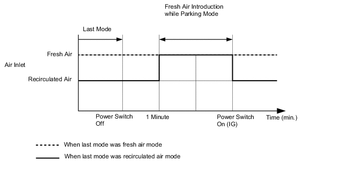
Fresh Air Introduction while Parking Mode
-
While parking, fresh air introduction mode is automatically selected to enhance ventilation and reduce any odor remaining in the air conditioning unit, minimizing odor during engine start-up.
Figure 2. Timing Chart (Sample)
-
-
-
DIAGNOSIS
-
In order to make system inspections easier to perform, a diagnosis function is used in consideration of serviceability. The Diagnostic Trouble Codes (DTCs) of malfunctions can be read by connecting the Global TechStream (GTS). For details, refer to the Repair Manual.
-