METER / GAUGE SYSTEM
-
OUTLINE
-
An 8-inch color Thin Film Transistor (TFT) Liquid Crystal Display (LCD) combination meter, which displays a dial and needle using an LCD, is used.
-
A 1-dial combination meter, which displays a digital speedometer and an analog tachometer, is used.
-
A tachometer, gauge and various vehicle information are displayed on a color TFT LCD monitor to achieve visibility and a pleasant design.
-
A movable meter ring, which can switch its displayed content, is used, and it can display 2 screens on 1 combination meter.
-
A movable meter ring that is moved by a motor is provided, enabling 2 types of display.
-
A multi-information display that shows various kinds of information is integrated.
-
The combination meter assembly has a built-in meter ECU and buzzer.
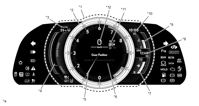
*1 8-inch Color TFT LCD Monitor *2 Movable Meter Ring *3 Outside Temperature Gauge *4 Hybrid System Indicator/MG Power Meter *5 Tachometer *6 Multi-information Display *7 Fuel Gauge *8 Odo/trip Meter *9 Engine Coolant Temperature Gauge *10 Clock *11 Shift Position Indicator *12 Speedometer *a The illustration shown is example only. The illustration may differ from the actual vehicle screen. - -
-
-
MAIN FEATURES
-
Movable Meter Ring
-
The combination meter assembly has 2 display modes: ring center display mode and ring side display mode.
-
Switching display modes is performed using the back/ring movable switch on the steering pad switch assembly. Returning to the previous display mode is performed using the back/ring movable switch again.
-
In ring center display mode, the movable meter ring is positioned at the center and the tachometer, speedometer, shift position indicator and multi-information display are displayed inside of the movable meter ring. In addition, the outside temperature gauge, hybrid system indicator/MG power meter, clock, odo/trip meter and gauges are displayed around the movable meter ring.
-
In ring side display mode, the movable meter ring moves to the right side of the display, the enlarged multi-information display is displayed at the left and the tachometer, speedometer, shift position indicator and odo/trip meter are displayed inside of the movable meter ring. In addition, the outside temperature gauge, clock and gauges are displayed at the top and bottom of the multi-information display.
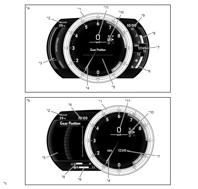
*1 Movable Meter Ring *2 Outside Temperature Gauge *3 Hybrid System Indicator/MG Power Meter *4 Tachometer *5 Multi-information Display *6 Fuel Gauge *7 Odo/trip Meter *8 Engine Coolant Temperature Gauge *9 Clock *10 Shift Position Indicator *11 Speedometer - - *a Ring Center Display Mode *b Ring Side Display Mode *c The illustration shown is example only. The illustration may differ from the actual vehicle screen. - -
-
-
Opening Ceremony
-
When the hybrid system starts, the needle of the tachometer in the movable meter ring is illuminated, and an animation is displayed on the LCD monitor.
-
After the animation completes, tachometer graduations, the speedometer and the shift position indicator are illuminated.
-
Next, an animation is displayed where gauges appear from both sides of the movable meter ring.
-
Afterward, the outside temperature gauge, clock, odo/trip meter and multi-information display are illuminated.
Tech Tips
The illustration is a representative example of the animation order. The display on the actual vehicle may differ depending on the power source mode status and the ring position memory settings.
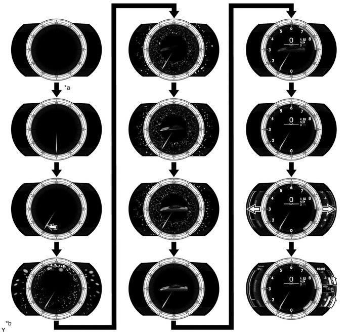
*a IG On (READY) *b The illustration shown is example only. The illustration may differ from the actual vehicle screen.
-
-
Ending Ceremony
-
When the power switch is turned off, the speedometer, the outside temperature gauge, the clock, some of the tachometer graduations and the gauge bar graphs are turned off.
-
Afterward, the multi-information display and gauge graduations are turned off.
-
When this occurs, an animation is displayed where the gauge frames appear to be stored into both sides of the movable meter ring.
-
Furthermore, the tachometer needle rotates counterclockwise, and then an animation is used to turn off the graduations of the tachometer.
-
Once the tachometer needle completes one rotation, all tachometer graduations and the shift position indicator are turned off in order.
-
Next, the tachometer needle fades out while turning off, moving inward from the end towards the center.
-
Afterward, the odo/trip meter and clock are illuminated, and once a certain period of time elapses, they are turned off.
Tech Tips
The illustration is a representative example of the animation order. The display on the actual vehicle may differ depending on the power source mode status and the ring position memory settings.
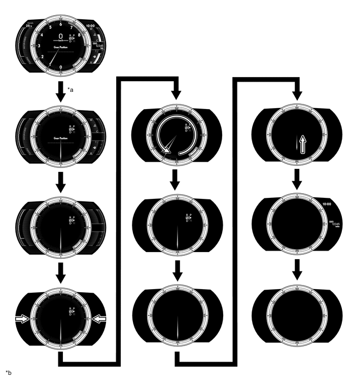
*a Off *b The illustration shown is example only. The illustration may differ from the actual vehicle screen.
-
-
Drive Mode
-
The drive mode indicator is displayed at the bottom right, inside the movable meter ring.
-
Driving modes can be selected by performing drive mode select operations.
-
When Eco mode is selected, the hybrid system indicator is displayed on the left side of the movable meter ring. Also, when a mode other than Eco mode is selected, the MG power meter is displayed.
-
When Sport S or Sport S+ mode is selected, the design of the tachometer dial changes according to each mode and the needle turns red.
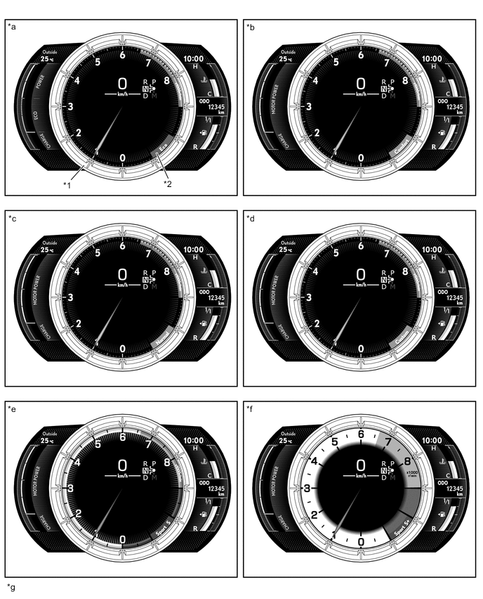
*1 Movable Meter Ring *2 Drive Mode Indicator *a Eco Mode *b Comfort Mode *c Normal Mode *d Custom Mode *e Sport S Mode *f Sport S+ Mode *g The illustration shown is example only. The illustration may differ from the actual vehicle screen. - -
-
-
Rev Indicator
-
A rev indicator, which notifies the driver when the engine speed exceeds a predetermined speed, is provided.
-
When the engine speed exceeds a set level, the rev indicator (yellow ring) is illuminated in the tachometer.
-
If the engine speed exceeds 6600 r/min, the rev indicator (red ring) is illuminated in the tachometer.
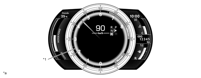
*1 Rev Indicator - - *a The illustration shown is example only. The illustration may differ from the actual vehicle screen. - -
-
-
Tachometer Peak Hold Display
-
The tachometer peak hold display, which displays the afterimage of the tachometer needle at the maximum engine speed, is provided.
-
If the engine speed is changed due to shift change operation, the afterimage of the maximum engine speed is displayed for 1 second.
-
This function operates when engine speed is 4000 r/min or more.
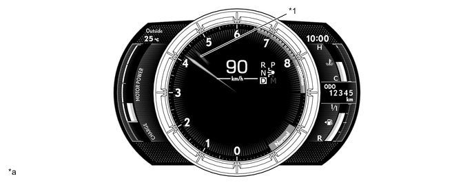
*1 Tachometer Peak Hold Display - - *a The illustration shown is example only. The illustration may differ from the actual vehicle screen. - -
-
-
Hybrid System Indicator (when in Eco Mode)
-
A hybrid system indicator, which displays the total of the engine output and Motor Generator (MG) output as the hybrid system output and the regeneration status, is provided.
-
The scale for the hybrid system indicator is divided into 3 areas (CHARGE, ECO, and POWER). The role of each area is as follows:
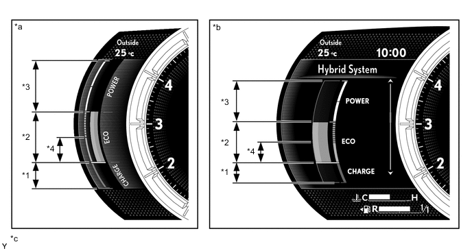
*1 CHARGE Area *2 ECO Area *3 POWER Area *4 HV ECO Area *a Ring Center Display Mode *b Ring Side Display Mode *c The illustration shown is example only. The illustration may differ from the actual vehicle screen. - - Information Displayed in Hybrid System Indicator Area Function CHARGE The CHARGE area indicates that energy is being regenerated. ECO
-
The ECO area indicates that the vehicle is being driven in an eco-friendly manner.
-
The HV ECO area indicates that the vehicle is driven in a manner that frequently uses only the motor. (Based on various conditions, the hybrid vehicle control ECU assembly controls if the engine should be stopped to enhance fuel efficiency.)
POWER The POWER area indicates that the eco-friendly driving range is being exceeded (during full power driving, etc.). -
-
-
MG Power Meter (when not in Eco Mode)
-
An MG power meter, which displays the Motor Generator (MG) output and regeneration status, is provided.
-
The scale for the MG power meter is divided into 2 areas (CHARGE and MOTOR POWER). The role of each area is as follows:
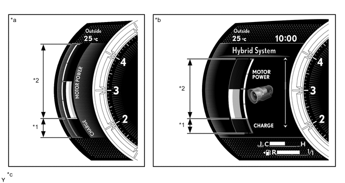
*1 CHARGE Area *2 MOTOR POWER Area *a Ring Center Display Mode *b Ring Side Display Mode *c The illustration shown is example only. The illustration may differ from the actual vehicle screen. - - Information Displayed in MG Power Meter Area Function CHARGE The CHARGE area indicates that energy is being regenerated. MOTOR POWER The MOTOR POWER area displays the Motor Generator (MG) output.
-
-
Gear Position Indicator
-
A graphic is used to display all transmission gear positions and the current gear position.
-
When the shift position is D, the changed gear position is automatically displayed in white and the current gear position is emphasized.
-
When a paddle shift operation is performed while the shift position is D, the unchanged gear positions are automatically grayed out and the current gear position is emphasized.
-
When the shift position is changed to M, the current gear position is emphasized by displaying it in orange and all other gear positions are grayed out.
-
When the shift position is P, R or N, all gear positions are grayed out.
Ring Center Display Mode Condition Gear Position Indicator Display Shift position is D 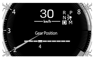
Paddle shift operation when shift position is D 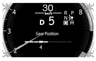
Shift position is M 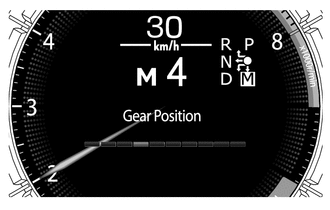
Shift position is P, R or N 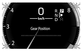
Ring Side Display Mode Condition Gear Position Indicator Display Shift position is D 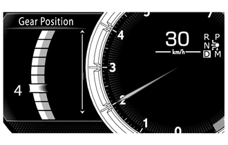
Paddle shift operation when shift position is D 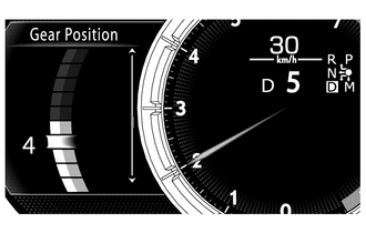
Shift position is M 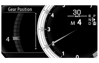
Shift position is P, R or N 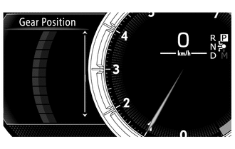
-
-
G Monitor
-
A G monitor, which uses numbers and a graphic to display the amount of front/rear and left/right gravitational acceleration applied to the vehicle, is provided.
-
When the ring center display mode is selected, the direction and amount of the gravitational acceleration are displayed.
-
When ring side display mode is selected, the amount and direction of the gravitational acceleration are displayed using a ball and number. Also, the G monitor can be switched between 1.0 G mode and 1.5 G mode to change the maximum gravitational acceleration value. When the G monitor is in 1.5 G mode, the trajectory of the ball indicating the maximum value is displayed on the screen.
Condition G Monitor Display Ring Center Display Mode 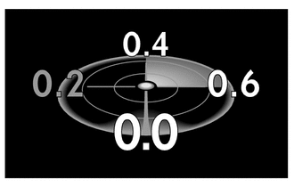
Ring Side Display Mode 1.0 G Mode 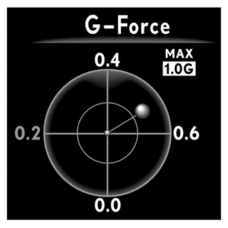
1.5 G Mode 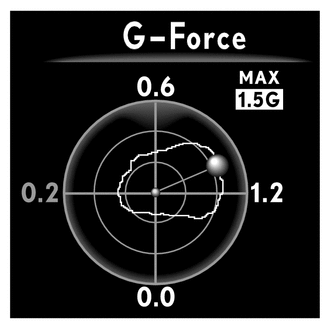
-
-
Liquid Crystal Display (LCD) Monitor
-
The following information can be displayed on the LCD monitor.
Item Outline Speedometer The vehicle speed is displayed. Tachometer The engine speed is displayed. Shift Position Indicator
-
The current shift position is displayed.
-
The recommended gear change timing is indicated.
Engine Coolant Temperature Gauge The engine coolant temperature is displayed. Fuel Gauge The remaining amount of fuel is displayed. Hybrid System Indicator The hybrid system output and regeneration status is displayed. MG Power Meter The MG output and regeneration status is displayed. ODO/TRIP Meter
-
The odometer, trip meter A, trip meter B, oil maintenance or speed warning display*1 is displayed.
-
The item shown can be switched by pressing the ODO/TRIP switch.
-
When the power switch is turned on (IG), the distance of the oil maintenance will display for 6 seconds.
-
When the oil maintenance notification condition is met, the distance of the oil maintenance is displayed via an interrupt screen.
Vehicle Power Source State
-
The vehicle power source state is displayed.
-
The key certification indicator is displayed on the multi-information display.
Outside Temperature Gauge
-
The outside temperature is displayed.
-
When the outside temperature drops below 3 °C (37 °F), an ice warning indicator illuminates to warn the driver to drive with caution due to possibly icy road conditions. After the ice warning indicator flashes 10 times, the indicator stays on. When the temperature reaches 5 °C (41 °F), the indicator goes off.
Clock The current time is displayed. Light Control Rheostat Meter panel luminance can be changed by using the rheostat switch. Indicator When the illumination conditions are met, the following indicators illuminate:
-
Cruise Control Indicator*2
-
Cruise Control Indicator (Constant Speed Control Mode)*3
-
Cruise Control Indicator (Vehicle-to-vehicle Distance Control Mode)*3
-
Cruise Control SET Indicator
-
LDA Indicator*4
-
LKA Indicator*5
-
Key Certification Indicator
-
Charge Warning Indicator*6
-
High Engine Coolant Temperature Indicator
-
Engine Oil Pressure Indicator
-
Brake Pad Wear Warning Indicator
-
Ice Warning Indicator
Drive Mode The currently selected drive mode is displayed:
-
Eco Mode
-
Comfort Mode
-
Normal Mode
-
Custom Mode
-
Sport S Mode
-
Sport S+ Mode
Multi-information Display (Ring Center Display Mode)
-
The drive information is displayed.
-
When a warning or advice message request is received, an interrupt screen is displayed.
Multi-information Display (Ring Side Display Mode)
-
The following information can be displayed on the multi-information display by switching the tabs:
-
Drive Information
-
Navigation Information*7
-
Audio Information
-
Driving Support System Information
-
Warning Message
-
Settings
-
When a telephone information*8, warning or advice message request is received, an interrupt screen is displayed.
*1: Models for Europe
*2: Models without Lexus Safety System+
*3: Models with Lexus Safety System+
*4: Models with Lane Departure Alert (LDA) system
*5: Models with Lane Keeping Assist (LKA) system
*6: Except models for China
*7: Models with navigation system
*8: This information can be displayed when a telephone is connected via Bluetooth.
-
-
-
Multi-information Display
-
When ring center display mode is selected, the multi-information display is displayed inside the movable meter ring positioned in the center. When ring side display mode is selected, the multi-information display is displayed on the left side, outside of the movable meter ring displayed on the right side.
-
The following information can be displayed on the multi-information display when the ring center display mode is selected.
Ring Center Display Mode Item Outline Drive Information
-
The following items can be displayed. The 4 display items can be selected in the setting screen:
-
Current Fuel Consumption (Bar Display)/Average Fuel Consumption (Mark Display)
-
Total Average Fuel Consumption Between Reset Operations
-
Average Fuel Consumption After Hybrid System Start-up
-
Average Fuel Consumption After Refueling
-
Total Average Vehicle Speed Between Reset Operations
-
Average Vehicle Speed After Hybrid System Start-up
-
Cruising Range After Hybrid System Start-up
-
Total Elapsed Time Between Reset Operations
-
Elapsed Time After Hybrid System Start-up
-
Cruising Range
-
In addition to the above functions, the following items can be displayed:
-
Tire Inflation Pressure Display
-
Gear Position Indicator
-
Unit Change*1, *2
-
G Monitor
-
Rear Wing Position*3
-
Blank
Tech Tips
*1: The unit displayed on the multi-information display can be selected by using the steering pad switch assembly.
-
MPH
-
km/h
*2: Destination package for United Kingdom
*3: Models with active rear wing system
-
-
The following information can be displayed by switching tabs on the multi-information display when the ring side display mode is selected. Furthermore, tabs are switched using the right and left switches of the steering pad switch assembly.
Ring Side Display Mode Item Outline Drive Information
-
The following items can be displayed. The 4 display items can be selected in the setting screen:
-
Current Fuel Consumption (Bar Display)/Average Fuel Consumption (Mark Display)
-
Total Average Fuel Consumption Between Reset Operations
-
Average Fuel Consumption After Hybrid System Start-up
-
Average Fuel Consumption After Refueling
-
Total Average Vehicle Speed Between Reset Operations
-
Average Vehicle Speed After Hybrid System Start-up
-
Cruising Range After Hybrid System Start-up
-
Total Elapsed Time Between Reset Operations
-
Elapsed Time After Hybrid System Start-up
-
Cruising Range
-
In addition to the above functions, the following items can be displayed:
-
Energy Monitor
-
Hybrid System Indicator/MG Power Meter
-
G Monitor
-
Gear Position Indicator
-
Vehicle Sway Warning*1
-
Tire Inflation Pressure Display
-
Rear Wing Position*2
-
Blank
Navigation Information*3 Navigation information is displayed. Audio Information Audio information (status information) is displayed and the audio source and songs can be switched. Driving Support System Information The operation condition of the following items is displayed:
-
Cruise Control System*4
-
Dynamic Radar Cruise Control System*1
-
Lane Departure Alert (LDA) System*5
-
Lane Keeping Assist (LKA) System*6
Warning Message Warning messages about vehicle malfunctions are displayed. Settings The following settings can be changed:
-
LDA (Lane Departure Alert System)*5
-
LKA (Lane Keeping Assist System)*6
-
PCS (Pre-Collision System)*1
-
BSM (Blind Spot Monitor System)*7
-
Parking Assist (Lexus Parking Assist-sensor System)
-
Speed Warning*8
-
RSA (Road Sign Assist System)*9
-
HUD (Head-Up Display) Brightness/Position*10
-
Unit Change
-
Clock
-
Vehicle Settings
-
Meter Settings
*1: Models with Lexus Safety System+
*2: Models with active rear wing system
*3: Models with navigation system
*4: Models without Lexus Safety System+
*5: Models with Lane Departure Alert (LDA) system
*6: Models with Lane Keeping Assist (LKA) system
*7: Models with Blind Spot Monitor (BSM) system
*8: Models for Europe
*9: Models with road sign assist system
*10: Models with headup display
-
-
-