HYBRID BATTERY SYSTEM
-
CONSTRUCTION
-
The HV battery (HV supply battery assembly) is composed of the No. 1 HV supply stack sub-assembly, No. 2 HV supply stack sub-assembly, battery ECU assembly, battery voltage sensor (upper and lower), battery cooling blower assembly, HV battery junction block assembly (System Main Relays (SMRs), HV battery current sensor and precharge resistor) and service plug grip.
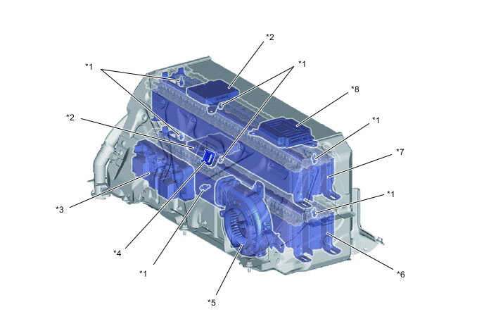
*1 HV Battery Temperature Sensor *2 Battery Voltage Sensor *3 HV Battery Junction Block Assembly
-
System Main Relays (SMRs)
-
HV Battery Current Sensor
-
Precharge Resistor
*4 Service Plug Grip *5 Battery Cooling Blower Assembly *6 No. 2 HV Supply Stack Sub-assembly *7 No. 1 HV Supply Stack Sub-assembly *8 Battery ECU Assembly -
-
Compact, lightweight 3.7 V lithium-ion battery cells are used in order to generate high power output.
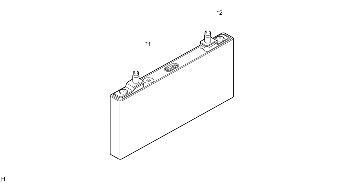
*1 Positive Terminal *2 Negative Terminal -
The 42 lithium-ion battery cells provided for each hybrid battery stack are connected in series in a bus bar module.
-
The HV battery (HV supply battery assembly) consists of 2 hybrid battery stacks. They are connected to each other in series through bus bar modules and wiring harness.
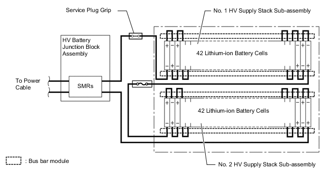
-
A dedicated battery cooling blower assembly is provided for the HV battery (HV supply battery assembly).
-
A service plug grip is provided to shut off the high-voltage circuit, ensuring safety during maintenance work.
-