TOYOTA PARKING ASSIST-SENSOR SYSTEM
Info Added 2017-04-18 ![]()
-
FUNCTION OF MAIN COMPONENTS
Component Function Clearance Warning ECU Assembly
-
Judges the approximate distance between the vehicle and an obstacle based on signals from the ultrasonic sensors. Output signals are sent to the multi-information display.
-
Sounds the No. 1 and No. 2 clearance warning buzzer.
Front Corner Ultrasonic Sensor (2) Detects the distance between the vehicle and an obstacle. Front Center Ultrasonic Sensor (2) Front Side Ultrasonic Sensor (2) Rear Corner Ultrasonic Sensor (2) Rear Center Ultrasonic Sensor (2) Rear Side Ultrasonic Sensor (2) Combination Meter Assembly TOYOTA Parking Assist-sensor System Indicator Light Illuminates to inform the driver when the system operation conditions are met. Multi-information Display
-
Displays the location of the obstacle and the approximate distance between the vehicle and the obstacle.
-
Displays an indication of a malfunction or freezing of an ultrasonic sensor to inform the driver.
Master Warning Light Illuminates in accordance with the indication on the multi-information display. Combination Meter Assembly Sends the TOYOTA parking assist-sensor system on/off signal to the clearance warning ECU assembly. No. 1 Clearance Warning Buzzer (Front) Sounds to inform the driver according to the distance to the obstacle. No. 2 Clearance Warning Buzzer (Rear) Steering Pad Switch Assembly Sends operation signals from switches to the spiral cable with sensor sub-assembly. Spiral Cable with Sensor Sub-assembly Sends operation signals from the steering pad switch assembly to the combination meter assembly. Steering Sensor Sends the steering angle signal to the clearance warning ECU assembly. Shift Lever Position Sensor Sends the shift position signals to the hybrid vehicle control ECU. Hybrid Vehicle Control ECU Transmits the shift position signals to the clearance warning ECU assembly. Brake Booster with Master Cylinder Assembly
-
Skid Control ECU
Sends the vehicle speed signal to the clearance warning ECU assembly. Airbag Sensor Assembly Sends the G information signal to the clearance warning ECU assembly. Air Conditioning Amplifier Assembly Sends outside temperature information to the clearance warning ECU assembly. Main Body ECU (Multiplex Network Body ECU)
-
Sends model destination signal (information to indicate the market the vehicle was built for) to the clearance warning ECU assembly.
-
Sends the parking brake signal to the clearance warning ECU assembly.
-
-
SYSTEM CONTROL
-
Detection Area
-
The detection areas of the ultrasonic sensor are as shown in the following illustration.
-
These detection areas are applicable when positioning a 60 mm (2.36 in.) diameter pole parallel or perpendicular to the ground. The ranges vary depending on the measuring method and type of obstacle.
Figure 1. Corner Area
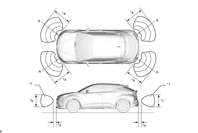
*a Approximately 500 mm (19.7 in.) *b Approximately 650 mm (25.6 in.) *c Approximately 550 mm (21.7 in.) *d Approximately 100 mm (3.9 in.) Note
The ultrasonic sensor side view detection range area (labeled*1) represents the cross section of the top view of the lines of detection range A. The area*1 does not represent the entire side view detection range.
Figure 2. Center Area
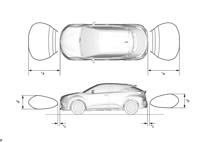
*a Approximately 1000 mm (39.4 in.) *b Approximately 650 mm (25.6 in.) *c Approximately 100 mm (3.9 in.) - - Figure 3. Sides Area
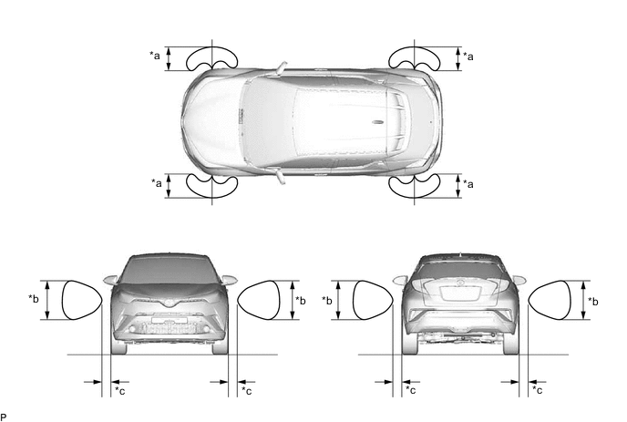
*a Approximately 1000 mm (39.4 in.) *b Approximately 400 mm (15.7 in.) *c Approximately 100 mm (3.9 in.) - -
-
-
The operating condition of each sensor differs according to its installed position as shown in the table below:
Installation Position Operating Condition Front Corner
-
Power switch is ON.
-
System is activated.*
-
Shift lever is in a position other than P.
-
Vehicle speed is approximately 10 km/h (6 mph) or less.
Front Center Front Side Rear Side Rear Corner
-
Power switch is ON.
-
System is activated.*
-
Shift lever is in R or has been shifted to N from R.
Rear Center *: Even if the back sonar or clearance sonar switch assembly is off, the system is activated when the simple-intelligent parking assist system is operating.
-
-
-
FUNCTION
-
TOYOTA Parking Assist-sensor System On/Off Setting
-
The TOYOTA parking assist-sensor system can be turned on or off via the setting screen displayed on the multi-information display.
-
The TOYOTA parking assist-sensor system indicator light is located in the combination meter assembly so that the driver can see whether the TOYOTA parking assist-sensor system is on. When the TOYOTA parking assist-sensor system is on, the TOYOTA parking assist-sensor system indicator light illuminates.
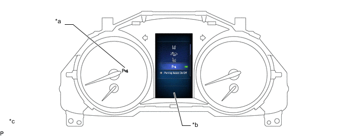
*a TOYOTA Parking Assist-sensor System Indicator Light *b Multi-information Display *c The illustration shown is an exampled only. The illustration may differ from the actual vehicle screen. - -
-
-
Detection Area Scan Display
-
After turning the power switch ON, the scanned detection areas (gray) are displayed on the multi-information display.
-
The detection areas are displayed for 3 seconds after the scan by all ultrasonic sensors is completed.
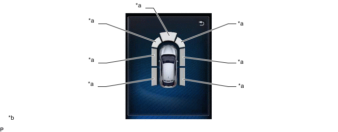
*a Scanned Detection Area *b The illustration shown is an example only. The illustration may differ from the actual vehicle screen. Tech Tips
The side detection areas are scanned by the side ultrasonic sensors while the vehicle is moving.
-
-
-
DIAGNOSIS
-
If a system malfunction is detected, the clearance warning ECU assembly stores Diagnostic Trouble Codes (DTCs) in its memory. For details, refer to the Repair Manual.
-