BODY STRUCTURE
Info Added 2017-04-18 ![]()
-
CONSTRUCTION
-
Front Wheel Opening Extension Pad
-
A front wheel opening extension pad is used to reduce the volume of air hitting against the rotating body of the tire. As a result, turbulence generated by the rotation of the front tire which disturbs the surrounding airflow has been suppressed, thus reducing air resistance and achieving a high level of straight-line stability at high speed.
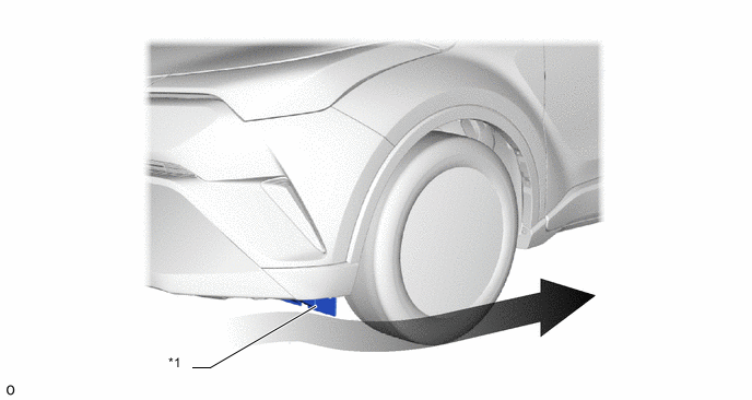
*1 Front Wheel Opening Extension Pad - - 
Airflow - -
-
-
Rear Wheel House Plate Front
-
A rear wheel house plate front is used to reduce the volume of air hitting against the rotating body of the tire. As a result, turbulence generated by the rotation of the rear tire which disturbs the surrounding airflow has been suppressed, thus reducing air resistance and achieving a high level of straight-line stability at high speed.
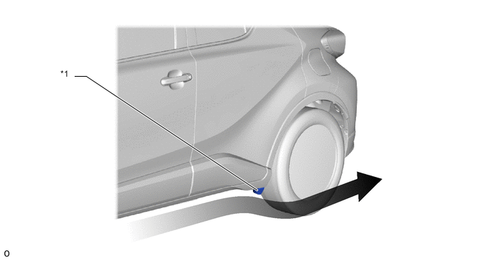
*1 Rear Wheel House Plate Front - - Airflow - -
-
-
Roof Spoiler
-
A roof spoiler with integrated high-mount stop light is available, realizing both excellent aerodynamic performance and an advanced design.
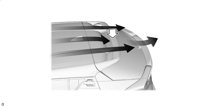
Airflow 
Down Force
-
-
Under Body
-
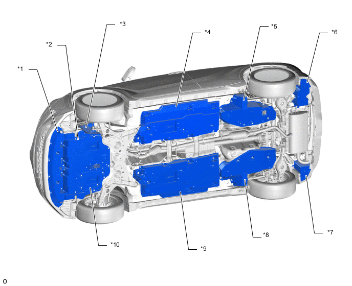
To create a smooth rearward airflow for the air which enters from the front to under floor, the following parts with airflow adjustment effects are located on the lower surface of the vehicle. Smooth airflow in the lower surface of the vehicle enhances the speed of airflow and a low pressure region is created between the vehicle and the road surface (Venturi effect). This low pressure region attracts the vehicle to the road surface, thus causing down force. Thus, superior straight-line stability has been achieved.
-
A flat airflow adjustment surface is provided for the engine under cover. Also, an aero stabilizing fin is provided.
-
The surface area of the engine under cover and floor covers has been increased, and the height from the ground has also been optimized. In addition, an aero stabilizing fin is provided.
Figure 1. Models for Europe
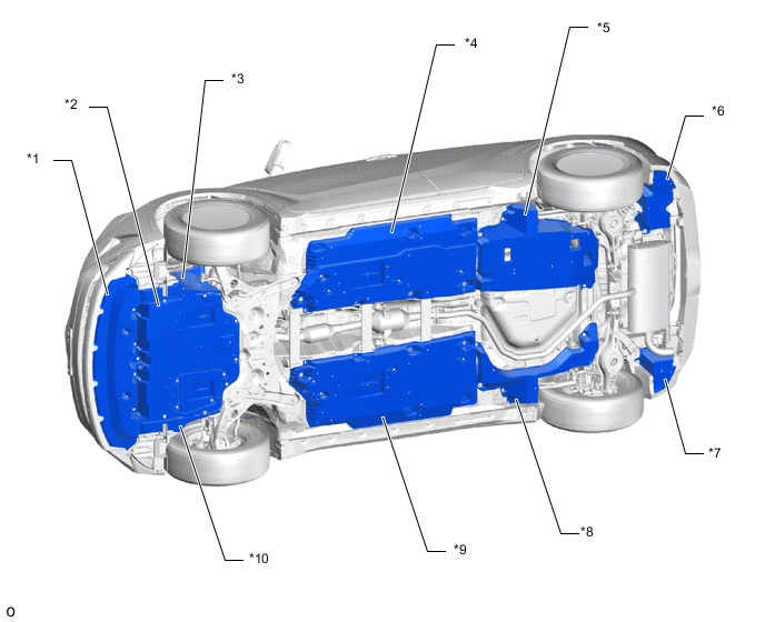
*1 No. 2 Engine Under Cover Assembly *2 No. 1 Engine Under Cover *3 Rear Engine Under Cover LH *4 Front Floor Cover LH *5 Rear Floor Side Member Cover LH *6 No. 2 Floor Under Cover *7 No. 1 Floor Under Cover *8 Rear Floor Side Member Cover RH *9 Front Floor Cover RH *10 Rear Engine Under Cover RH Figure 2. Except Models for Europe
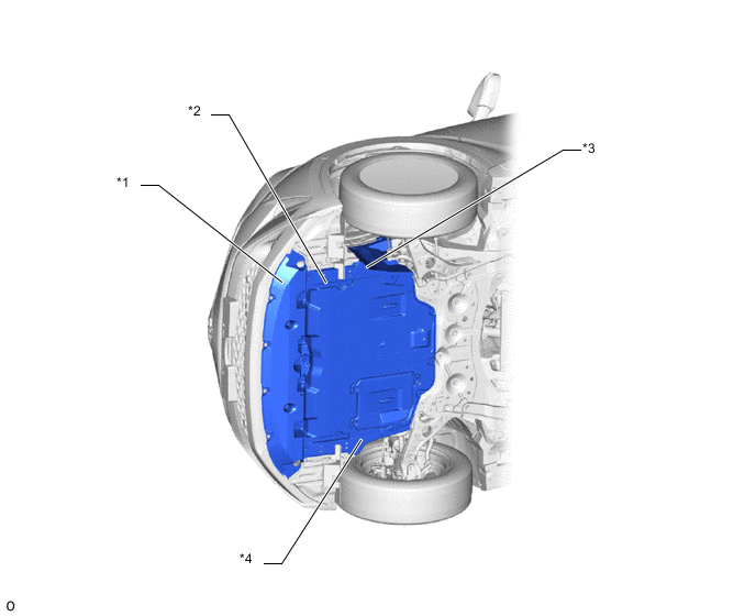
*1 No. 2 Engine Under Cover Assembly *2 No. 1 Engine Under Cover *3 Rear Engine Under Cover LH *4 Rear Engine Under Cover RH Figure 3. AWD Models
*1 No. 2 Engine Under Cover Assembly *2 No. 1 Engine Under Cover *3 Rear Engine Under Cover LH *4 Front Floor Cover LH *5 Rear Floor Side Member Cover LH *6 No. 2 Floor Under Cover *7 No. 1 Floor Under Cover *8 Rear Floor Side Member Cover RH *9 Front Floor Cover RH *10 Rear Engine Under Cover RH -
-
-