DYNAMIC TORQUE CONTROL AWD SYSTEM
Info Added 2017-04-18 ![]()
-
FUNCTION OF MAIN COMPONENTS
Component Function Transmission Coupling Assembly 4WD Linear Solenoid Distributes drive torque in accordance with the amperage applied by the 4WD ECU assembly. Spiral Cable with Sensor Sub-assembly Steering Sensor Detects the direction and angle of the steering wheel. Speed Sensor Detects the wheel speed of each wheel. Stop Light Switch Assembly Detects the brake pedal depressing signal. Crank Position Sensor Assembly Detects the engine speed and outputs it to the ECM. Throttle Body with Motor Assembly Throttle Position Sensor Detects the throttle valve position and outputs it to the ECM. Park/Neutral Position Switch Assembly Detects the shift position of the transaxle and outputs it to the ECM. Airbag Sensor Assembly Yawrate Sensor Detects the vehicle's yaw rate. Deceleration Sensor Detects the vehicle's longitudinal and lateral deceleration. 4WD ECU Assembly Controls the amperage applied to the 4WD linear solenoid based on signals provided by the ECUs, sensors and switches in order to optimally distribute drive torque in accordance with driving conditions. ECM Outputs signals such as the shift position signal, throttle position signal and engine speed signal to the 4WD ECU assembly. Skid Control ECU Outputs signals such as the vehicle speed signal and brake pedal depressing signal to the 4WD ECU assembly. Combination Meter Assembly Multi-information Display Informs the driver that the 4WD ECU assembly has a malfunction in the system. Master Warning Light Informs the driver that the 4WD ECU assembly has a malfunction in the system. -
SYSTEM CONTROL
Control Function Start Off Control Performs control which distributes drive force to the rear wheels to ensure traction performance when starting off and avoid the tight corner braking phenomenon*, which occurs during cornering. Normal Control
-
Performs control which distributes drive force to the rear wheels to ensure acceleration performance when driving straight ahead and cornering stability.
-
When a stable driving condition has been determined, reduces drive force distribution to the rear wheels to improve fuel economy.
Cornering Control Uses pre-torque control, which is based on driver operation input, and yawrate feedback control, which is based on the vehicle status, to achieve the tracing performance desired by the driver. Braking Control When braking, cancels AWD to improve braking effectiveness. VSC Cooperative Control When accelerating during cornering on slippery surfaces, etc., the dynamic torque control AWD system and VSC function cooperate to perform control which achieves smoother acceleration and higher stability compared to previous TRC and VSC functions. As a result, smooth acceleration during turning is made possible. Tech Tips
*: Tight corner braking phenomenon: a phenomenon in which an AWD vehicle may lurch and decelerate due to a rotational speed difference between the front and rear wheels, such as during low-speed cornering in AWD mode.
-
Start Off Control
-
The system ensures start-off performance by optimally distributing engine drive torque to the front and rear wheels.
-
To prevent the tight corner braking phenomenon from occurring during low-speed cornering, the system reduces the amount of torque distributed to the rear wheels.
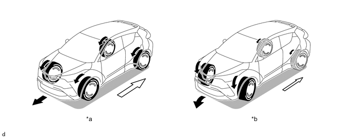
*a Straightline Driving *b Low-speed Cornering 
Torque Distribution to Rear Wheels - -
-
-
Normal Control
-
During normal driving, when the system judges that the vehicle is traveling steadily, it reduces the amount of torque distribution to the rear wheels. This allows the vehicle to operate in conditions similar to front-wheel-drive, improving fuel economy.
-
The system optimizes torque distribution to the rear wheels to provide both excellent straightline acceleration performance and excellent driving stability while cornering.
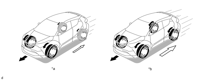
*a Steady Driving *b Straightline Acceleration Torque Distribution to Rear Wheels - -
-
-
Cornering Control
-
The desired driving path of the driver is estimated using information such as the vehicle speed, steering angle, etc., to change drive force distribution according to driving conditions. As a result, driving stability is enhanced.
-
Pre-torque control, which is based on driver operation input, and yawrate feedback control, which is based on the vehicle status, are used to correct vehicle oversteer and understeer and achieve the tracing performance desired by the driver.
-
Pre-torque control is linked with driver steering wheel operations and distributes drive force to the rear wheels to improve steering performance when entering a corner (front and rear drive force distribution is 90:10).
-
Yawrate feedback control performs high-speed computation of the ideal yaw rate (calculated by the 4WD ECU assembly when the vehicle is in motion) and actual yaw rate, detects vehicle steering characteristics (oversteer or understeer), and performs optimal control to distribute drive force to the front or rear wheels if required for correction (front and rear drive force distribution changes from 90:10 to 50:50).
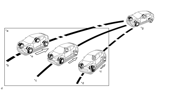
*a Yawrate Feedback Control *b Understeer Tendency *c Target Line *d Oversteer Tendency *e Drive Force Distribution to Rear Wheels Increased *f Drive Force Distribution to Rear Wheels Reduced *g Pre-torque Control - -
-
-
-
FUNCTION
-
AWD Operation Condition Display
-
The operation condition of the AWD system, which automatically operates according to the longitudinal acceleration, lateral acceleration and steering angle of the vehicle during driving, is shown on the multi-information display.
-
The user can recognize how the AWD system is operating in response to various conditions, even on slippery roads. This contributes to improved safety while driving with the AWD system.
-
The driver can operate the steering pad switch to select whether to display or hide the AWD system operation condition.
Multi-information Display Outline 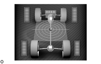
-
Drive force, which the AWD system distributes to front and rear wheels, varies depending on the driving conditions.
-
The amount of drive force applied to each wheel is displayed in segments.
-
The number of displayed segments increases when the drive force applied to each wheel is large, and decreases when it is small.
-
When the drive force applied to the rear wheels is large, the capabilities of the AWD system are being utilized in conditions that require start-off and driving performance.
-
When the drive force applied to the rear wheels is small, the system has determined that driving conditions are stable and the AWD system is being restrained in order to improve fuel economy.
-
Longitudinal and lateral acceleration, which vary depending on the driving conditions, are indicated by the position of a sphere over concentric circles placed at the center of the vehicle.
-
The condition of the vehicle is indicated by the position of the sphere relative to the center of the concentric circles as shown below.
-
Front: decelerating, rear: accelerating, right side: turning left, left side: turning right
-
-
-
-
FAIL-SAFE
-
When there is a possibility of causing damage to the drivetrain due to a malfunction in the AWD system or rough driving, the system illuminates or blinks the master warning light and displays the massage on the multi-information display to inform the driver and stops AWD control.
Vehicle Condition Control Combination Meter Assembly Master Warning Light Multi-information Display AWD system malfunction 2WD driving
(control prohibited)
Illuminates AWD System
Malfunction
2WD Mode
Engaged
Visit Your Dealer
AWD excess driving (warning before AWD control is prohibited) AWD driving Blinks AWD System
Overheated
Switching to
2WD Mode
AWD excess driving 2WD driving
(control prohibited)
Blinks AWD System
Overheated
2WD Mode
Engaged
-
When the master warning light illuminates or blinks as a message is displayed on the multi-information display, perform the following procedures.
-
Decelerate until the master warning light turns off.
-
Stop the vehicle until the master warning light turns off (idle the engine).
-
-
When a stable system condition is determined, AWD control automatically resumes.
-
-
DIAGNOSIS
-
The 4WD ECU assembly will also store a Diagnostic Trouble Code (DTC). The DTC can be accessed through the use of a Global TechStream (GTS). For details, refer to the Repair Manual.
-