BRAKE SYSTEM
-
CONSTRUCTION
-
For models with 8NR-FTS engine or 3ZR-FAE engine, a vacuum pump assembly has been provided.
-
For the VALVEMATIC used in 3ZR-FAE engine vehicles, the throttle valve remains open during operation, and engine output is controlled mainly on the intake valve side, it can sometimes become difficult to generate vacuum. For this reason, in models with 3ZR-FAE engines the vacuum pump assembly generates the vacuum necessary for the brake booster assembly to perform boosting.
-
Due to turbocharging, the 8NR-FTS engine is unable to derive sufficient vacuum pressure from the intake system. For this reason, in models with 8NR-FTS engines the vacuum pump assembly generates the vacuum necessary for the brake booster assembly to perform boosting.
-
The vacuum pump assembly is composed of an elliptically-shaped housing, a rotor and a vane. By using a single vane, when compared to a pump with multiple blades, the pumping volume within the housing is larger so that pumping ability is improved, and the reduced diameter rotor also achieves reduced weight.
-
The vacuum pump assembly is installed to the cylinder head sub-assembly, and is driven by the camshaft.
Figure 1. Models with 3ZR-FAE Engine
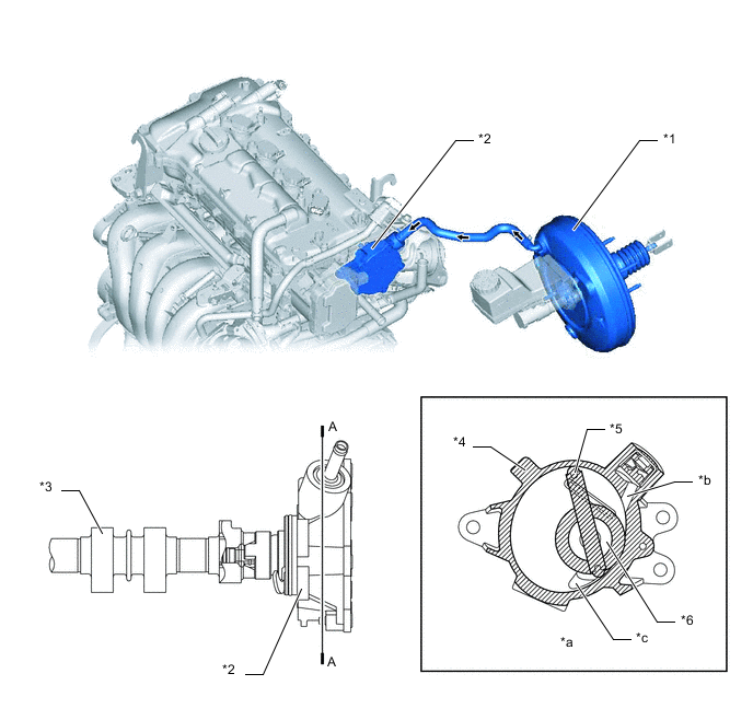
*1 Brake Booster Assembly *2 Vacuum Pump Assembly *3 Exhaust Camshaft *4 Housing *5 Vane *6 Rotor *a A-A Cross Section *b Inlet *c Outlet - - Figure 2. Models with 8NR-FTS Engine
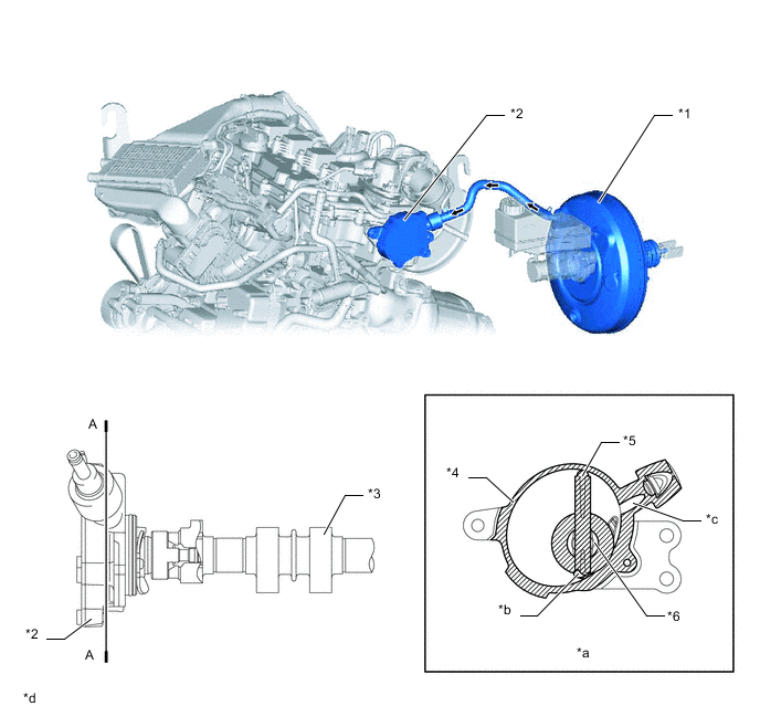
*1 Brake Booster Assembly *2 Vacuum Pump Assembly *3 Exhaust Camshaft *4 Housing *5 Vane *6 Rotor *a A-A Cross Section *b Outlet *c Inlet *d The illustrations shown are examples only.
-
-
OPERATION
-
As the vane slides up and down through the channel in the rotor, it rotates along the inner wall of the housing. As the housing is elliptical, the volume of each of the 2 chambers partitioned by the vane changes as the vane rotates.
-
Labeling the 2 chambers partitioned by the vane as chamber A and chamber B, the rotation of the vane causes the volume of chamber A to decrease, and air is expelled through the outlet. Conversely, the volume of chamber B increases and air is sucked out into the pump through the inlet. The vacuum pump operates by repeating this process.
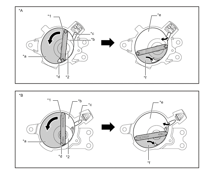
*A Models with 3ZR-FAE Engine *B Models with 8NR-FTS Engine *1 Vane *2 Rotor *a Chamber A *b Chamber B *c Inlet *d Outlet *e Chamber B (Volume: Increases) *f Chamber A (Volume: Decreases)
-