BRAKE CONTROL SYSTEM
-
CONSTRUCTION
-
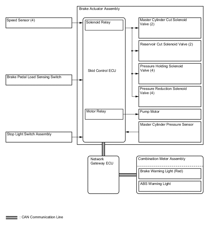
The brake actuator consists of the actuator portion and skid control ECU.
-
The actuator portion regulates the hydraulic brake pressure to each wheel cylinder.
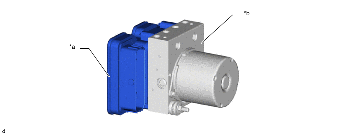
*a Skid Control ECU *b Actuator Portion -
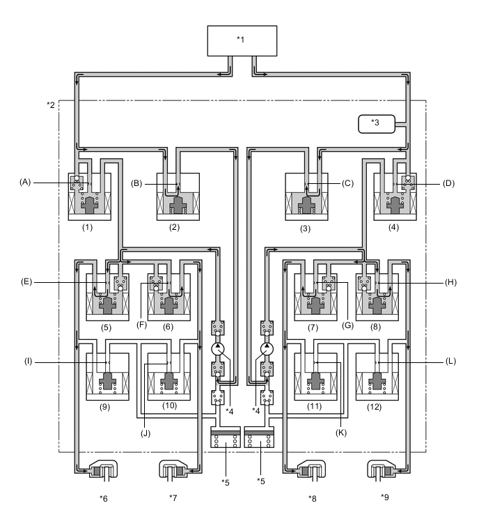
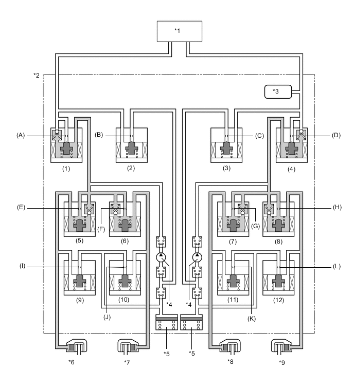
The brake actuator is constructed with the following hydraulic circuit:
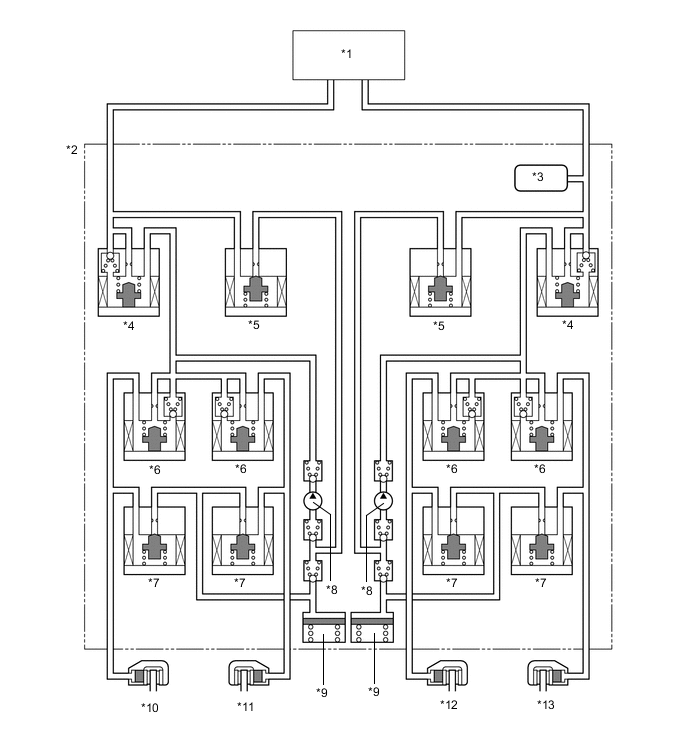
*1 Brake Master Cylinder Sub-assembly *2 Brake Actuator Assembly *3 Master Cylinder Pressure Sensor *4 Master Cylinder Cut Solenoid Valve *5 Reservoir Cut Solenoid Valve *6 Pressure Holding Solenoid Valve *7 Pressure Reduction Solenoid Valve *8 Pump *9 Reservoir *10 Front Brake Caliper (Right Side) *11 Rear Brake Caliper (Left Side) *12 Rear Brake Caliper (Right Side) *13 Front Brake Caliper (Left Side) - -
-
-
OPERATION
-
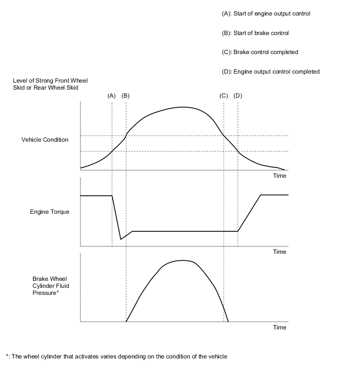
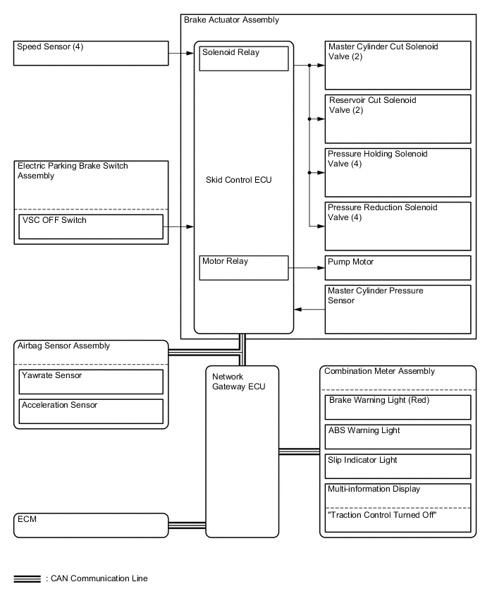
Engine Output Control during TRC or VSC Operation
-
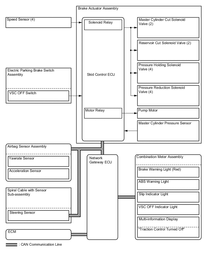
During the TRC or VSC operation, the skid control ECU outputs the engine output control signal to the ECM. Upon receiving this signal, the ECM inhibits the engine output.
-
-
ABS with EBD
-
Based on the signals received from the 4 speed sensors, the skid control ECU calculates each wheel speed and deceleration, and checks wheel slipping conditions. According to the slipping condition, the skid control ECU controls the pressure holding valve and pressure reduction valve in order to adjust the fluid pressure of each wheel cylinder in the following 3 modes: pressure reduction, pressure holding and pressure increase modes.
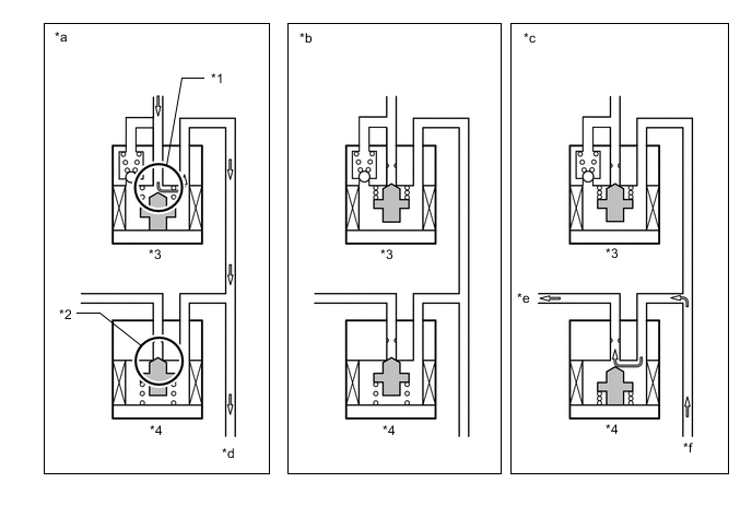
*1 Port A *2 Port B *3 Pressure Holding Solenoid Valve *4 Pressure Reduction Solenoid Valve *a Increase Mode *b Holding Mode *c Reduction Mode *d to Wheel Cylinder *e to Reservoir and Pump *f from Wheel Cylinder Not Activated Normal Braking - - Activated Increase Mode Holding Mode Reduction Mode Pressure Holding Solenoid Valve (Port A) OFF (Open) ON (Close) ON (Close) Pressure Reduction Solenoid Valve (Port B) OFF (Close) OFF (Close) ON (Open) Wheel Cylinder Pressure Increased Held Reduced
-
-
Brake Assist
-
In the event of emergency braking, the skid control ECU determines the driver's intentions based on the speed of the pressure increase in the master cylinder detected by the master cylinder pressure sensor signal. If the skid control ECU judges the need for additional brake assist, pressure to supplement the amount provided by the master cylinder is generated by the pump in the brake actuator and directed to each wheel cylinder.
*1 Brake Master Cylinder Sub-assembly *2 Brake Actuator Assembly *3 Master Cylinder Pressure Sensor *4 Pump *5 Reservoir *6 Front Brake Caliper (Right Side) *7 Rear Brake Caliper (Left Side) *8 Rear Brake Caliper (Right Side) *9 Front Brake Caliper (Left Side) - - -
Each valve operates as shown below:
Item Port Brake Assist Not Activated Brake Assist Activated Master Cylinder Cut Solenoid Valve (1), (4) (A), (D) OFF (Open) ON* Reservoir Cut Solenoid Valve (2), (3) (B), (C) OFF (Closed) ON (Open) Front Brakes Pressure Holding Solenoid Valve (5), (8) (E), (H) OFF (Open) OFF (Open) Pressure Reduction Solenoid Valve (9), (12) (I), (L) OFF (Closed) OFF (Closed) Rear Brakes Pressure Holding Solenoid Valve (6), (7) (F), (G) OFF (Open) OFF (Open) Pressure Reduction Solenoid Valve (10), (11) (J), (K) OFF (Closed) OFF (Closed) Pump OFF ON Tech Tips
*: Hydraulic pressure is controlled by continuously cycling the solenoid valves between open and closed, according to the operating conditions.
-
-
TRC
-
The fluid pressure generated by the pump is regulated by the master cylinder cut solenoid valve to achieve the required pressure. Thus, the brakes for the drive wheels are controlled in the following 3 modes: pressure reduction, pressure holding, and pressure increase modes, to control slippage of the drive wheels.
-
The diagram shows the hydraulic circuit in pressure increase mode when TRC is activated. The pressure holding solenoid valve and the pressure reduction solenoid valve are turned ON/OFF according to the ABS and EBD operation pattern.
*1 Brake Master Cylinder Sub-assembly *2 Brake Actuator Assembly *3 Master Cylinder Pressure Sensor *4 Pump *5 Reservoir *6 Front Brake Caliper (Right Side) *7 Rear Brake Caliper (Left Side) *8 Rear Brake Caliper (Right Side) *9 Front Brake Caliper (Left Side) - - -
Each valve operates as shown below:
Item Port TRC Not Activated TRC Activated Increase Mode Holding Mode Reduction Mode Master Cylinder Cut Solenoid Valve (1), (4) (A), (D) OFF (Open) ON* ON* ON* Reservoir Cut Solenoid Valve (2), (3) (B), (C) OFF (Closed) ON (Open) ON (Open) ON (Open) Front Brakes Pressure Holding Solenoid Valve (5), (8) (E), (H) OFF (Open) OFF (Open) ON (Closed) ON (Closed) Pressure Reduction Solenoid Valve (9), (12) (I), (L) OFF (Closed) OFF (Closed) OFF (Closed) ON (Open) Brake Wheel Cylinder Pressure - - - Increased Held Reduced Rear Brakes Pressure Holding Solenoid Valve (6), (7) (F), (G) OFF (Open) ON (Closed) ON (Closed) ON (Closed) Pressure Reduction Solenoid Valve (10), (11) (J), (K) OFF (Closed) ON (Open) ON (Open) ON (Open) Brake Wheel Cylinder Pressure - - - - - - Pump OFF ON ON ON Tech Tips
*: Hydraulic pressure is controlled by continuously cycling the solenoid valves between open and closed, according to the operating conditions.
-
-
VSC
-
VSC, by way of solenoid valves, controls the fluid pressure generated by the pump and applies it to each wheel cylinder in the following 3 modes: pressure reduction, pressure holding, and pressure increase modes. As a result, understeer and oversteer tendencies are controlled.
-
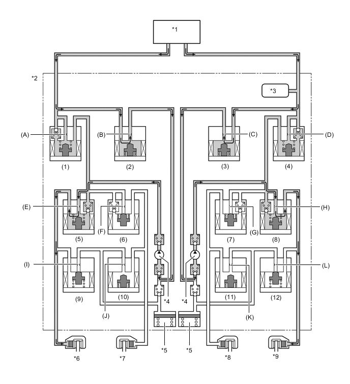
In understeer restraining control, the skid control ECU controls engine output and applies the brakes of the front and rear wheel on the inside of the turn. Also, depending on whether the brakes are applied and the vehicle condition, there are circumstances in which the brake of a specific wheel may not be applied even if it was targeted for braking. The diagram below shows the hydraulic circuit in pressure increase mode, as it restrains an understeer tendency while the vehicle is making a right turn. In other operating modes, the pressure holding valve and the pressure reduction valve are turned ON/OFF according to the ABS and EBD operation pattern.
Figure 1. VSC Operation (Understeer Restraining Control)
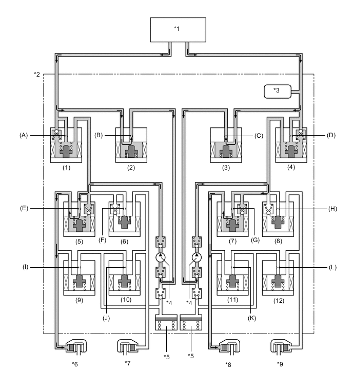
*1 Brake Master Cylinder Sub-assembly *2 Brake Actuator Assembly *3 Master Cylinder Pressure Sensor *4 Pump *5 Reservoir *6 Front Brake Caliper (Right Side) *7 Rear Brake Caliper (Left Side) *8 Rear Brake Caliper (Right Side) *9 Front Brake Caliper (Left Side) - - -
Each valve operates as shown below:
Item Port VSC Not Activated VSC Activated Increase Mode Holding Mode Reduction Mode Master Cylinder Cut Solenoid Valve (1), (4) (A), (D) OFF (Open) ON* ON* ON* Reservoir Cut Solenoid Valve (2), (3) (B), (C) OFF (Closed) ON (Open) ON (Open) ON (Open) Front Brake Pressure Holding Solenoid Valve (5) (E) OFF (Open) OFF (Open) ON (Closed) ON (Closed) (8) (H) OFF (Open) ON (Closed) ON (Closed) ON (Closed) Pressure Reduction Solenoid Valve (9) (I) OFF (Closed) OFF (Closed) OFF (Closed) ON (Open) (12) (L) OFF (Closed) OFF (Closed) OFF (Closed) OFF (Closed) Brake Wheel Cylinder Pressure Right - - Increased Held Reduced Left - - Increased Held Reduced Rear Brake Pressure Holding Solenoid Valve (6) (F) OFF (Open) ON (Closed) ON (Closed) ON (Closed) (7) (G) OFF (Open) OFF (Open) ON (Closed) ON (Closed) Pressure Reduction Solenoid Valve (10) (J) OFF (Closed) OFF (Closed) OFF (Closed) OFF (Closed) (11) (K) OFF (Closed) OFF (Closed) OFF (Closed) ON (Open) Brake Wheel Cylinder Pressure Right - - Increased Held Reduced Left - - - - - Pump OFF ON ON ON Tech Tips
*: Hydraulic pressure is controlled by continuously cycling the solenoid valves between open and closed, according to the operating conditions.
-
In oversteer restraining control, the skid control ECU applies the brakes of the front and rear wheels on the outside of the turn. Also, depending on whether the brakes are applied and the vehicle condition, the brake of a specific wheel may not be applied even if it was targeted for braking. The diagram below shows the hydraulic circuit in pressure increase mode, as it restrains an oversteer tendency while the vehicle is making a right turn. In other operating modes, the pressure holding valve and the pressure reduction valve are turned ON/OFF according to the ABS and EBD operation patterns.
Figure 2. VSC Operation (Oversteer Restraining Control)
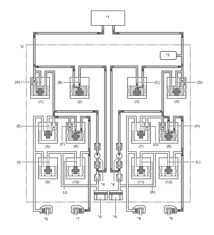
*1 Brake Master Cylinder Sub-assembly *2 Brake Actuator Assembly *3 Master Cylinder Pressure Sensor *4 Pump *5 Reservoir *6 Front Brake Caliper (Right Side) *7 Rear Brake Caliper (Left Side) *8 Rear Brake Caliper (Right Side) *9 Front Brake Caliper (Left Side) - - -
Each valve operates as shown below:
Item Port VSC Not Activated VSC Activated Increase Mode Holding Mode Reduction Mode Master Cylinder Cut Solenoid Valve (1), (4) (A), (D) OFF (Open) ON* ON* ON* Reservoir Cut Solenoid Valve (2), (3) (B), (C) OFF (Closed) ON (Open) ON (Open) ON (Open) Front Brake Pressure Holding Solenoid Valve (5) (E) OFF (Open) ON (Closed) ON (Closed) ON (Closed) (8) (H) OFF (Open) OFF (Open) ON (Closed) ON (Closed) Pressure Reduction Solenoid Valve (9) (I) OFF (Closed) OFF (Closed) OFF (Closed) OFF (Closed) (12) (L) OFF (Closed) OFF (Closed) OFF (Closed) ON (Open) Brake Wheel Cylinder Pressure Right - - - - - Left - - Increased Held Reduced Rear Brake Pressure Holding Solenoid Valve (6) (F) OFF (Open) OFF (Open) ON (Closed) ON (Closed) (7) (G) OFF (Open) ON (Closed) ON (Closed) ON (Closed) Pressure Reduction Solenoid Valve (10) (J) OFF (Closed) OFF (Closed) OFF (Closed) ON (Open) (11) (K) OFF (Closed) OFF (Closed) OFF (Closed) OFF (Closed) Brake Wheel Cylinder Pressure Right - - - - - Left - - Increased Held Reduced Pump OFF ON ON ON Tech Tips
*: Hydraulic pressure is controlled by continuously cycling the solenoid valves between open and closed, according to the operating conditions.
-
-
Trailer Sway Control Operation
-
The operation of the solenoid valves under the trailer sway control is the same as the VSC operation.
-
-
Hill-start Assist Operation
-
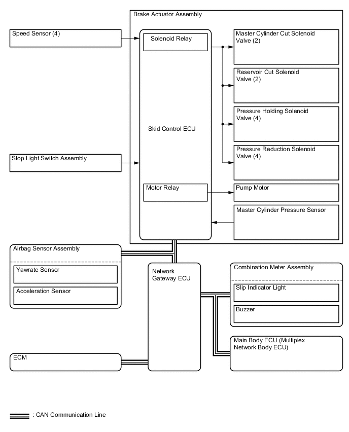
When hill-start assist control is operating, the skid control ECU holds the brake fluid pressure.
-
Based on the information provided by various sensors, switches, and the ECM, the skid control ECU determines whether to activate hill-start assist control.
-
During hill-start assist control, the slip indicator light blinks and the stop lights are illuminated.
*1 Brake Master Cylinder Sub-assembly *2 Brake Actuator Assembly *3 Master Cylinder Pressure Sensor *4 Pump *5 Reservoir *6 Front Brake Caliper (Right Side) *7 Rear Brake Caliper (Left Side) *8 Rear Brake Caliper (Right Side) *9 Front Brake Caliper (Left Side) - - Item Port Not Activated Hill-start Assist Control Activated Holding Mode Reduction Mode Master Cylinder Cut Solenoid Valve (1), (4) (A), (D) OFF (Open) ON* ON* Reservoir Cut Solenoid Valve (2), (3) (B), (C) OFF (Closed) OFF (Closed) OFF (Closed) Front Brakes Pressure Holding Solenoid Valve (5), (8) (E), (H) OFF (Open) OFF (Open) OFF (Open) Pressure Reduction Solenoid Valve (9), (12) (I), (L) OFF (Closed) OFF (Closed) OFF (Closed) Brake Wheel Cylinder Pressure - - Hold Reduce Rear Brakes Pressure Holding Solenoid Valve (6), (7) (F), (G) OFF (Open) OFF (Open) OFF (Open) Pressure Reduction Solenoid Valve (10), (11) (J), (K) OFF (Closed) OFF (Closed) OFF (Closed) Brake Wheel Cylinder Pressure - - Hold Reduce Pump OFF OFF OFF Tech Tips
*: Hydraulic pressure is controlled by continuously cycling the solenoid valves between open and closed, according to the operating conditions.
-
-
Brake Hold
-
The operation of the solenoid valves under the brake hold is the same as the operation of the hill-start assist control.
-
-
Cooperative Control with EPS
-
The operation of the solenoid valves under the steering cooperative control is the same as the TRC or VSC operation.
-
-
Dynamic Radar Cruise Control Brake
-
The skid control ECU operates the brakes by receiving a motive force request signal from the millimeter wave radar sensor assembly while the dynamic radar cruise control system is activated. This brake control operates in the same way as a normal brake operation.
-
-
Pre-collision Brake
-
If the millimeter wave radar sensor assembly determines that the possibility of a collision is high, the ECU sends a pre-collision brake assist request signal to the skid control ECU. Upon receiving the signal, the skid control ECU switches the brake assist to standby mode. When the driver depresses the brake pedal, the skid control ECU operates the brake assist based on the master cylinder pressure sensor.
-
If a collision is unavoidable, the skid control ECU actuates the motor in the power supply portion to apply direct pressure to the wheel cylinders even if the driver does not depress the brake pedal. This brake control operates in the same way as a normal brake operation.
-
-