CVT SYSTEM
-
CONSTRUCTION
-
The widths of the grooves of the pulleys are changed through hydraulic control.
-
During acceleration, the operation of the linear solenoid valve SLP increases the oil pressure of the primary pulley, thus decreasing the width of the pulley groove.
-
During deceleration, the operation of the linear solenoid valve SLP decreases the oil pressure of the primary pulley, thus increasing the width of the pulley groove.
-
The secondary pulley is hydraulically controlled by the linear solenoid valve SLS. It controls the belt clamping pressure to ensure the proper power transmission efficiency.
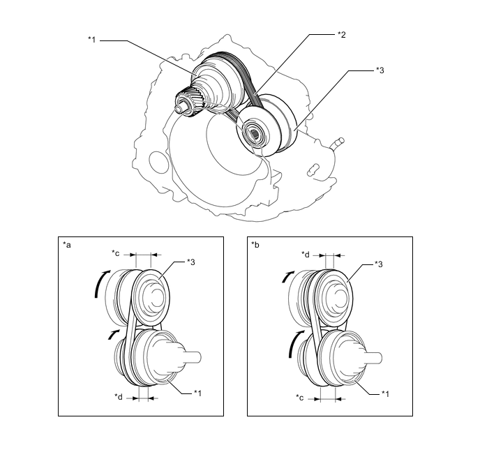
*1 Secondary Pulley *2 Steel Belt *3 Primary Pulley - - *a Pulley Ratio (Low) *b Pulley Ratio (High) *c Groove Width (Large) *d Groove Width (Small) -
The primary pulley uses a single piston construction.
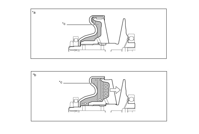
*a Pulley Ratio (Low) *b Pulley Ratio (High) *c Chamber - - -
The steel belt consists of elements and 2 rows of steel rings. In contrast to chains and belts, which transmit power through the use of tensile force, this steel belt uses the compressive action (pushing force) of the elements to transmit power.
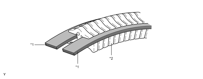
*1 Steel Ring *2 Element
-
-
OPERATION
-
The changing of the pulley ratio is accomplished in a continuously variable manner by varying the widths of the grooves of the primary and secondary pulleys.
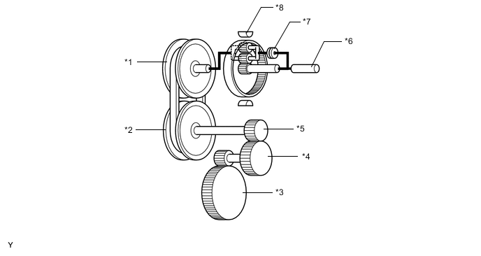
*1 Primary Pulley *2 Secondary Pulley *3 Differential Ring Gear *4 Reduction Driven Gear *5 Reduction Drive Gear *6 Input Shaft *7 Forward Clutch *8 Reverse Brake -
Shift Lever in D (Pulley Ratio Low)
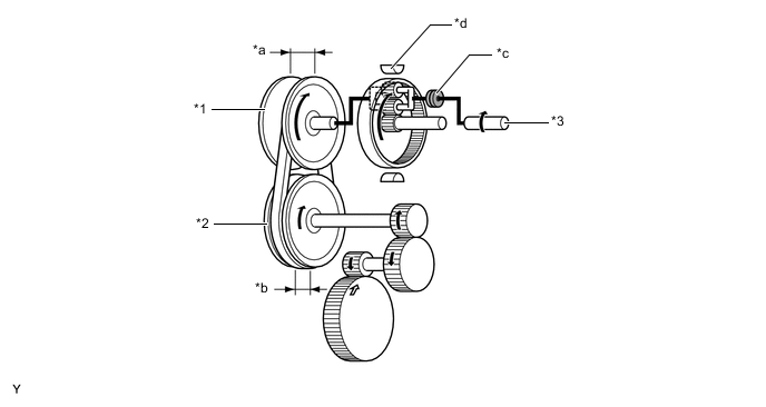
*1 Primary Pulley *2 Secondary Pulley *3 Input Shaft - - *a Groove Width (Large) *b Groove Width (Small) *c Forward Clutch (On) *d Reverse Brake (Off) -
Shift Lever in D (Pulley Ratio High)
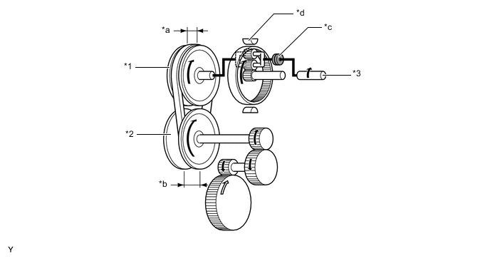
*1 Primary Pulley *2 Secondary Pulley *3 Input Shaft - - *a Groove Width (Small) *b Groove Width (Large) *c Forward Clutch (On) *d Reverse Brake (Off) -
Shift Lever in N
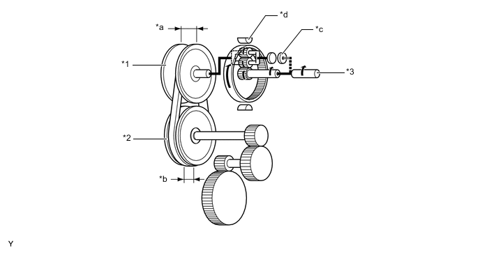
*1 Primary Pulley *2 Secondary Pulley *3 Input Shaft - - *a Groove Width (Large) *b Groove Width (Small) *c Forward Clutch (Off) *d Reverse Brake (Off) -
Shift Lever in R
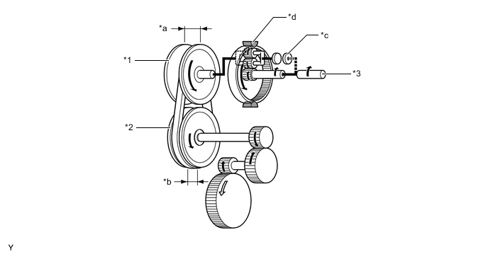
*1 Primary Pulley *2 Secondary Pulley *3 Input Shaft - - *a Groove Width (Large) *b Groove Width (Small) *c Forward Clutch (Off) *d Reverse Brake (On) -
Shift Lever in M
-
Gear train movement when the shift lever is in M is similar to the one when the shift lever is in D. However, since pulley ratio is adjusted in accordance with driver's shift operation, the driver is able to upshift or downshift with a manual-like feel.
-
-