CVT SYSTEM
-
CONSTRUCTION
-
The transmission valve body assembly consists of upper and lower valve bodies and 5 shift solenoid valves.
-
The 5 shift solenoid valves are installed in the lower valve body for serviceability.
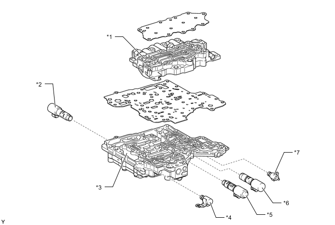
*1 Upper Valve Body *2 Linear Solenoid Valve SLU (for Lock-up Control) *3 Lower Valve Body *4 On-off Solenoid Valve SC (for Clutch Control) *5 Linear Solenoid Valve SLP (for Primary Pulley Control) *6 Linear Solenoid Valve SLS (for Secondary Pulley Control) *7 On-off Solenoid Valve SL (for Lock-up Control) - - 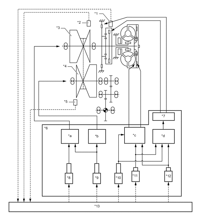
*1 Transmission Revolution Sensor (NT) *2 Transmission Revolution Sensor (NIN) *3 Primary Pulley *4 Secondary Pulley *5 Transmission Revolution Sensor (NOUT) *6 Valve Body *7 Manual Valve *8 Linear Solenoid Valve SLP (for Primary Pulley Control) *9 Linear Solenoid Valve SLS (for Secondary Pulley Control) *10 Linear Solenoid Valve SLU (for Lock-up Control) *11 On-off Solenoid Valve SL (for Lock-up Control) *12 On-off Solenoid Valve SC (for Clutch Control) *13 ECM - - *a Pulley Ratio Control *b Belt Clamping Pressure Control *c Lock-up Control *d Clutch Pressure Control
-
-
OPERATION
-
Belt Clamping Pressure Control Circuit
-
To ensure the proper control of the belt clamping pressure necessary for transmitting torque, the system controls the hydraulic pressure applied to the secondary pulley. The transmission valve body assembly is provided with a dedicated hydraulic pressure circuit for belt clamping pressure control. This circuit optimally controls the hydraulic pressure applied to the secondary pulley, thus achieving superior torque transmission performance.
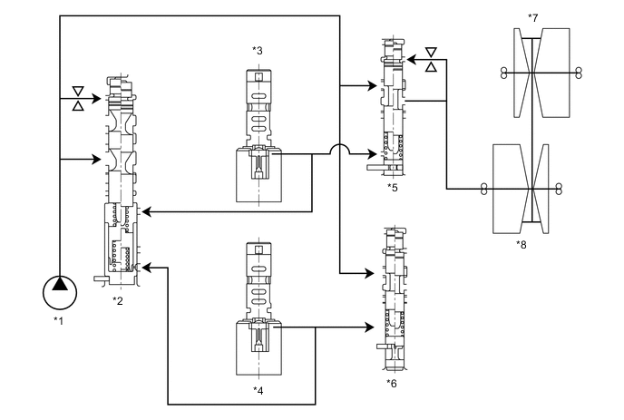
*1 Oil Pump Assembly *2 Primary Regulator Valve *3 Linear Solenoid Valve SLS (for Secondary Pulley Control) *4 Linear Solenoid Valve SLP (for Primary Pulley Control) *5 No. 1 Line Pressure Modulator Valve *6 No. 3 Line Pressure Modulator Valve *7 Primary Pulley *8 Secondary Pulley
-
-
Pulley Ratio Control Circuit
-
Pulley ratio control is performed by controlling the inflow and outflow of the CVT fluid to the primary pulley. Separate hydraulic circuits are provided for acceleration (fluid inflow) and deceleration (fluid outflow) in order to provide fine-tuned control and a high level of reliability.
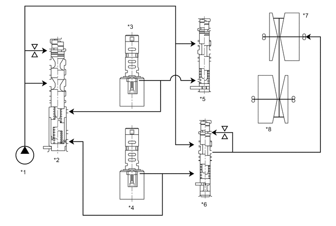
*1 Oil Pump Assembly *2 Primary Regulator Valve *3 Linear Solenoid Valve SLS (for Secondary Pulley Control) *4 Linear Solenoid Valve SLP (for Primary Pulley Control) *5 No. 1 Line Pressure Modulator Valve *6 No. 3 Line Pressure Modulator Valve *7 Primary Pulley *8 Secondary Pulley
-
-
Lock Up Control
-
Lock-up control is performed by controlling the oil pressure of the lock-up clutch. The on-off solenoid valve SL and linear solenoid valve SLU are provided to control the lock-up clutch.
-
-