EMISSION CONTROL SYSTEM
-
FUNCTION OF MAIN COMPONENTS
-
The main components of the blowby gas ventilation system are as follows:
Component Function Ventilation Valve Sub-assembly Opens and closes the valve using vacuum generated in the intake manifold and controls the flow rate of the blowby gas.
-
-
SYSTEM CONTROL
-
By introducing blowby gas that has a large amount of HC into the air intake and burning it again, the system attempts to enhance the emission performance. The volume of returned blowby gas is regulated to the appropriate amount corresponding to the engine operating conditions, reducing the volume of engine oil consumed and the impact on the engine idle speed.
-
The ventilation valve sub-assembly passage returns blowby gas into the area after the throttle valve in accordance with the intake manifold vacuum.
-
When the engine load is low, the passage from the cylinder head cover sub-assembly to the area before the throttle valve increases the air purification performance inside the crankcase by introducing fresh air, and when the engine load is high, the passage circulates the blowby gas together with the ventilation valve sub-assembly side passage due to the intake manifold vacuum.
-
An oil separator is located in the cylinder block sub-assembly. This contributes to the compactness of the entire engine.
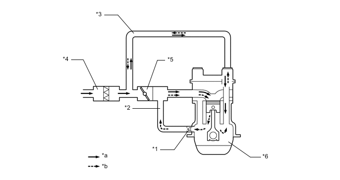
*1 Ventilation Valve Sub-assembly *2 Ventilation Hose *3 No. 2 Ventilation Hose *4 Air Cleaner Assembly *5 Throttle Body Assembly *6 Crankcase *a Fresh Air *b Blowby Gas
-