ENGINE UNIT
Info Added 2017-04-18 ![]()
-
CONSTRUCTION
-
Each VVT-i controller (camshaft timing gear assembly and camshaft timing exhaust gear assembly) consists of a housing driven by the chain sub-assembly and a vane coupled with the intake or exhaust camshaft.
-
Both the intake and exhaust sides have a 4-blade vane.
-
The oil pressure sent from the advanced or retarded side path at the intake and exhaust camshafts causes rotation in the VVT-i controller vane circumferential direction to allow for continuous vibration of the intake and exhaust valve timing.
-
When the engine is stopped, a lock pin locks the intake camshaft at the most retarded position and the exhaust camshaft at the most advanced position in order to enhance startability.
-
An advance assist spring is provided on the exhaust side VVT-i controller (camshaft timing exhaust gear assembly). This spring applies torque in the advance direction when the engine is stopped, thus ensuring engagement of the lock pin.
Figure 1. Intake VVT-i Controller (Camshaft Timing Gear Assembly)
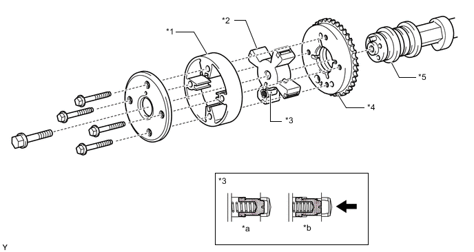
*1 Housing *2 Vane (Fixed on Intake Camshaft) *3 Lock Pin *4 Sprocket *5 Intake Camshaft - - *a At a Stop *b In Operation 
Oil Pressure - - Figure 2. Exhaust VVT-i Controller (Camshaft Timing Exhaust Gear Assembly)
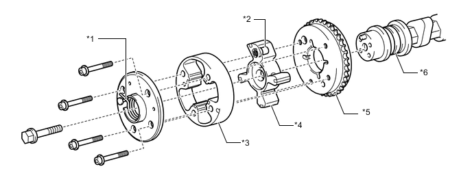
*1 Advance Assist Spring *2 Lock Pin *3 Housing *4 Vane (Fixed on Exhaust Camshaft) *5 Sprocket *6 Exhaust Camshaft
-
-
OPERATION
-
Advance
-
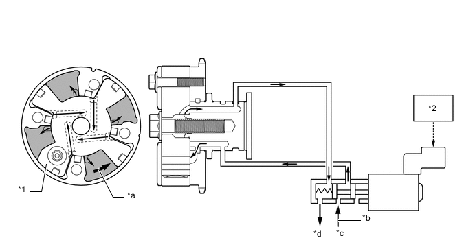
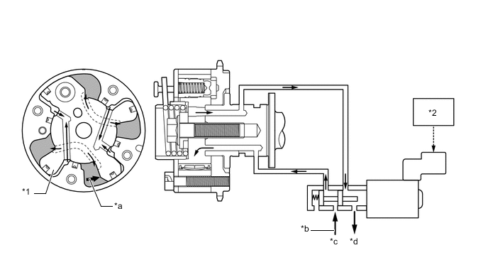
When the camshaft timing oil control valve assembly is positioned as shown in the illustration below by the advance signal from the ECM, the resultant oil pressure is applied to the timing advance side vane chamber to rotate the camshaft in the timing advance direction:
Figure 3. Intake Side
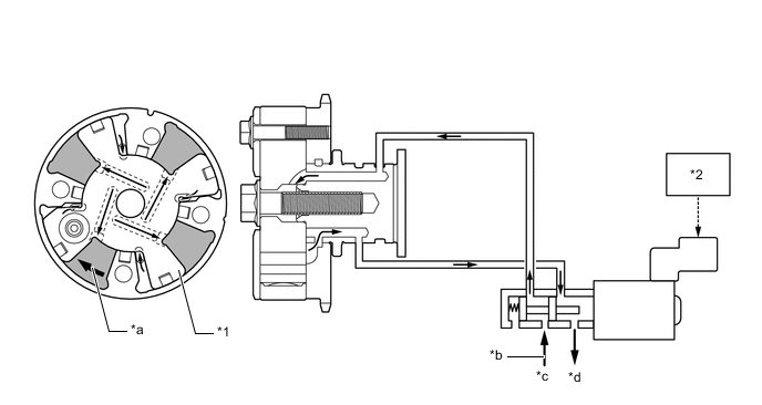
*1 Vane *2 ECM *a Rotation Direction *b Oil Pressure *c In *d Drain Figure 4. Exhaust Side
*1 Vane *2 ECM *a Rotation Direction *b Oil Pressure *c In *d Drain
-
-
Retard
-
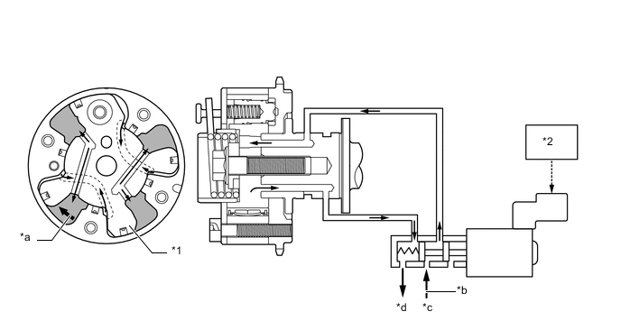
When the camshaft timing oil control valve assembly is positioned as illustrated below by the retard signals from the ECM, the resultant oil pressure is applied to the timing retard side vane chamber to rotate the camshaft in the timing retard direction:
Figure 5. Intake Side
*1 Vane *2 ECM *a Rotation Direction *b Oil Pressure *c In *d Drain Figure 6. Exhaust Side
*1 Vane *2 ECM *a Rotation Direction *b Oil Pressure *c In *d Drain
-
-
Hold
-
After reaching the target timing, the engine valve timing is maintained by keeping the camshaft timing oil control valve assembly in the neutral position unless the engine operating conditions change. This maintains the engine valve timing at the desired target position by prevents the engine oil from running out of the camshaft timing oil control valve assembly.
-
-