ENGINE UNIT
Info Added 2017-04-18 ![]()
-
CONSTRUCTION
-
Intake and exhaust efficiency has been increased due to larger total port areas.
-
Valve lash adjuster assemblies, which maintain a constant zero valve clearance through the use of oil pressure and spring force, are used.
-
A valve spring (inner compression spring), whose upper portion is shaped like a beehive, is used to reduce inertial mass. As a result, the load on the valve spring (inner compression spring) and friction are reduced.
-
The intake and exhaust camshafts are driven by a chain sub-assembly.
-
This engine uses the VALVEMATIC system which effects continuously variable control of the amount of intake valve lift and the intake valve action angle, and the dual Variable Valve Timing-intelligent (VVT-i) system, which controls the intake and exhaust valve timing. Through coordinated control, these systems optimally control the valve timing and amount of intake valve lift in accordance with the driving conditions. This achieves lower fuel consumption, higher engine performance and reduced exhaust emissions.
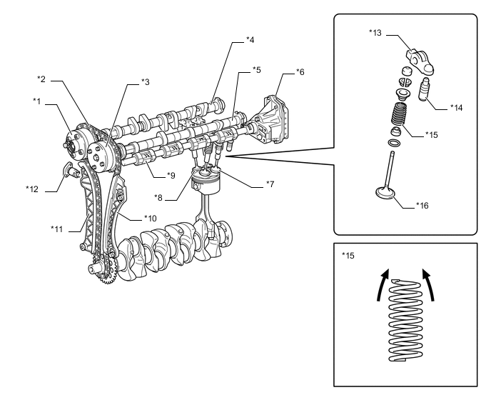
*1 Exhaust VVT-i Controller (Camshaft Timing Exhaust Gear Assembly) *2 Chain Sub-assembly *3 Intake VVT-i Controller (Camshaft Timing Gear Assembly) *4 Exhaust Camshaft (No. 2 Camshaft) *5 Intake Camshaft (Camshaft) *6 Continuously Variable Valve Lift Controller Assembly *7 Intake Valve *8 Exhaust Valve *9 VALVEMATIC Mechanism *10 No. 1 Chain Vibration Damper *11 Chain Tensioner Slipper *12 No. 1 Chain Tensioner Assembly *13 No. 1 Valve Rocker Arm Sub-assembly *14 Valve Lash Adjuster Assembly *15 Valve Spring (Inner Compression Spring) *16 Valve 
Beehive - - -
The intake and exhaust camshafts are made of a cast iron alloy.
-
An oil passage is provided in the intake and exhaust camshafts in order to supply engine oil to the VVT-i system.
-
The VVT-i controllers (camshaft timing gear assembly and camshaft timing exhaust gear assembly) have been installed on each front of the intake and exhaust camshafts to vary the timing of the intake and exhaust valves.
-
Together with the use of the No. 1 valve rocker arm sub-assembly, the cam profile has been designed with an indented R (radius). This results in increased valve lift when the valve begins to open and finishes closing, helping to achieve enhanced output performance.
-
A timing rotor for the cam position sensor is provided at each back end of the intake and exhaust camshafts.
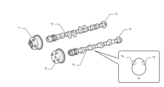
*1 Exhaust VVT-i Controller (Camshaft Timing Exhaust Gear Assembly) *2 Exhaust Camshaft (No. 2 Camshaft) *3 Timing Rotor *4 Intake Camshaft (Camshaft) *5 Intake VVT-i Controller (Camshaft Timing Gear Assembly) - - *a Cam with Indented R *b Indented R Portion of Cam (Profile)
-