ENGINE UNIT
Info Added 2017-04-18 ![]()
-
CONSTRUCTION
-
An aluminum alloy cylinder block sub-assembly with cast-iron liners is used to achieve size and weight reduction.
-
The liners are the spiny-type, which have been manufactured so that their casting exteriors form large irregular surfaces in order to enhance the adhesion between the liners and the aluminum cylinder block. The enhanced adhesion helps heat dissipation, resulting in a lower overall temperature and heat deformation of the cylinder bores.
-
The angle of the bore cross hatching, the polishing on the cylinder liner surface, is at an angle of 30°, thus improving the oil retention of the interior of the cylinder bore. This reduces the friction between the cylinder bore and the piston, improving fuel consumption.
-
The following items have been optimized to support the buildup of combustion pressure due to supercharging.
-
The basic structure of the engine, such as the thickness of the cylinder bore walls, the depth of the water jackets and the cylinder block ribs, has been optimized to achieve high rigidity and weight reduction. Also, the roundness of the cylinder bore and the angle of both axis of the crankshaft journals have been improved.
-
The sizes of the cylinder head bolt and crankshaft bearing cap bolt have been optimized.
-
A water passage, which directs coolant from the exhaust side to the intake side, is provided between each cylinder bore to improve cooling between the cylinder bores. The water passage angle has been optimized compared to Natural Aspiration (NA) engines to cool the cylinder bores, which become extremely hot when the pistons are at top dead center. As a result, heat is evenly dispersed in the direction of the circumference of the cylinder bore walls, and when driving, deformation of the cylinder bores is suppressed, friction is reduced and fuel economy and performance are improved.
-
The shape of the ribs, the knock control sensor installation boss position and the shape of the boss have been optimized to improve knocking control.
-
A No. 1 oil separate chamber is provided on the cylinder block side surface to support the increase in blowby gas volume due to supercharging and improve the efficiency of separating engine oil from the blowby gas.
-
Engine vibration has been reduced by reinforcing the ribs around the connection parts of the transaxle and improving the rigidity of the entire powertrain.
-
-
A thermostat (cylinder block side) is installed in the cylinder block to reduce piston and piston ring sliding resistance, which quickly raises the temperature of the cylinder bores, and improve fuel economy by reducing the engine coolant flow rate to the cylinder block sub-assembly when warming up the engine.
-
A direct coolant path is provided in the engine side module (water inlet housing) to the cylinder head sub-assembly and cylinder block sub-assembly and the distribution of engine coolant is optimized to prevent extreme increases in the temperature around the combustion chambers of the cylinder head sub-assembly and cylinder block sub-assembly when the thermostat (cylinder block side) installed in the cylinder block sub-assembly is closed.
-
A large breather hole is provided in the No. 1 to No. 4 journal wall. As a result, friction is reduced and output performance is improved at high engine speeds.
-
A drilled passage is provided between each cylinder bore to enhance bore cooling performance. This allows heat to be distributed evenly around the cylinder bore walls, reducing deformation of cylinder bores due to temperature differences when the engine is running. As a result, reduced friction, enhanced fuel economy and engine performance are achieved.
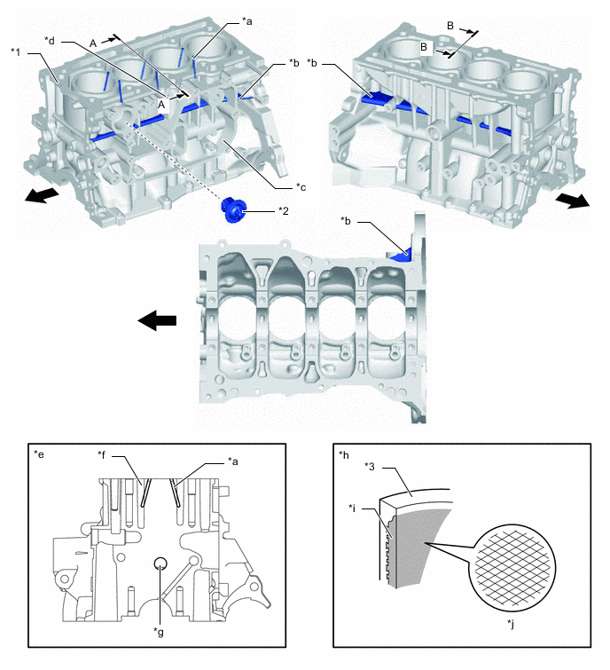
*1 Cylinder Block Sub-assembly *2 Thermostat (Cylinder Block Side) *3 Cylinder Bore - - *a Water Passage *b Rib *c No. 1 Oil Separate Chamber *d Knock Control Sensor Installation Boss *e A - A Cross Section *f Water Jacket *g Larger Breather Hole *h B - B Cross Section *i Spiny-type Liner (Irregularly Shaped Outer Casting Surface of Liner) *j Bore Cross Hatch 
Engine Front Side - - Figure 1. Coolant Passage
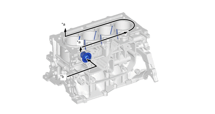
*a To Cylinder Head Sub-assembly *b From Engine Water Pump Assembly -
The oil passage from cylinder head sub-assembly to the stiffening crankcase assembly has been moved closer to the water jacket. This enhances heat transfer between engine oil and coolant, reducing the engine oil temperature. As a result, the need for an engine oil cooler has been eliminated.
Figure 2. Engine Oil and Coolant Passage
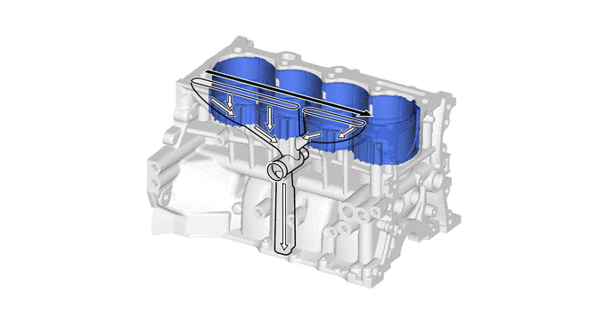
Coolant Flow 
Engine Oil Flow -
2 separate oil galleries, a main oil gallery for the crank journal oil passage and a sub oil gallery for the piston jet oil passage, are used. This allows the engine oil for the piston jets (No. 1 oil nozzle sub-assemblies) to be controlled by the oil pressure switching valve assembly, independent of the engine oil for the crank journals.
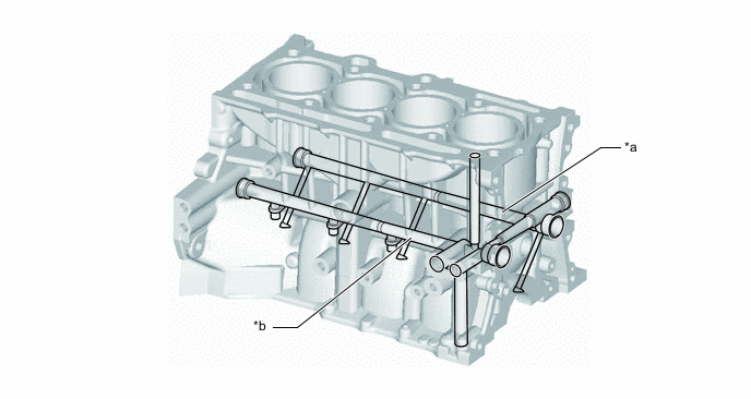
*a Main Oil Gallery *b Sub Oil Gallery -
The maximum combustion pressure is efficiently transmitted by using an offset crankshaft, where the center of the crankshaft is placed away from the center of the cylinder bore. Also, low fuel consumption is achieved by improving heat efficiency using piston speed changes and reducing the piston side force to reduce friction loss. Friction loss is reduced by efficiently transmitting the maximum combustion pressure to the crankshaft while reducing the force on the piston in the thrust direction during the combustion cycle.
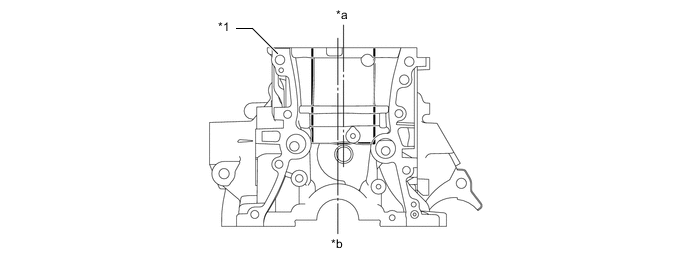
*1 Cylinder Block Sub-assembly - - *a Bore Center *b Crankshaft Center 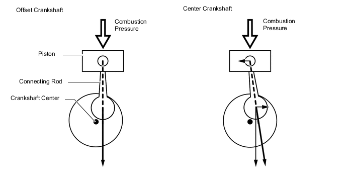
-