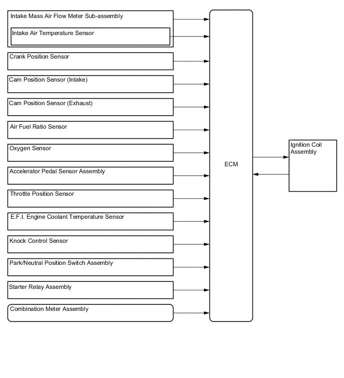
SFI SYSTEM
-
FUNCTION
-
The optimum ignition timing is selected according to signals from the sensors and the ignition signal (IGt) is sent to the igniter.
-
The ignition timing can be expressed using the following equation. The ignition timing is set initially to 10° BTDC.
Ignition Timing = A. Initial Set Ignition Timing or B. Basic Advanced Angle + C. Corrected Advanced Angle A. Fixed Advanced Angle Characteristics Fixed to 5° BTDC when starting the engine. The service terminals are short-circuited, and it is fixed to 10° BTDC when the throttle is closed. B. Basic Advanced Angle Characteristics Selects the optimum ignition timing, depending on each sensor signal. C. Correction Advanced Angle Characteristics Selects the appropriate advanced or retarded angles according to the engine status at that time, depending on each sensor signal. C-1. Warm-up Advanced Angle Characteristics Sets the ignition timing to advanced angle according to the operating status to improve drivability, when the coolant temperature is low. C-2. Idling Stability Advanced Angle Characteristics Sets the ignition timing to advance to stabilize idle speed when the idle speed is low. Also, as the speed gets higher, the ignition timing is retarded. C-3. Knocking Correction Retarded Angle When knocking is generated, the ignition timing is corrected according to a signal from the knock control sensor. -
If engine knocking is detected, the ignition timing is retarded gradually in equal steps according to the size of knocking, until the engine stops knocking.
-
After knocking has stopped, the ignition timing is advanced gradually in equal steps. If the engine knocks again during this process, then the ignition timing is retarded again.
Figure 1. Knocking Feedback Control Cycle
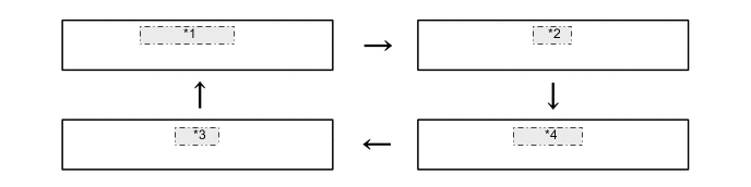
*1 Knocking Occurs *2 Retard *3 Advance *4 No Knocking
-