SFI SYSTEM
-
CONSTRUCTION
-
A Magneto Resistive Element (MRE) type crank position sensor is used to detect the engine speed and crankshaft angle.
-
The crank angle sensor plate (timing rotor) of the crankshaft consists of 34 teeth with 2 teeth missing. The crank position sensor outputs a crankshaft rotation signal every 10°, and the change of the signal due to the missing teeth is used to determine top-dead-center.
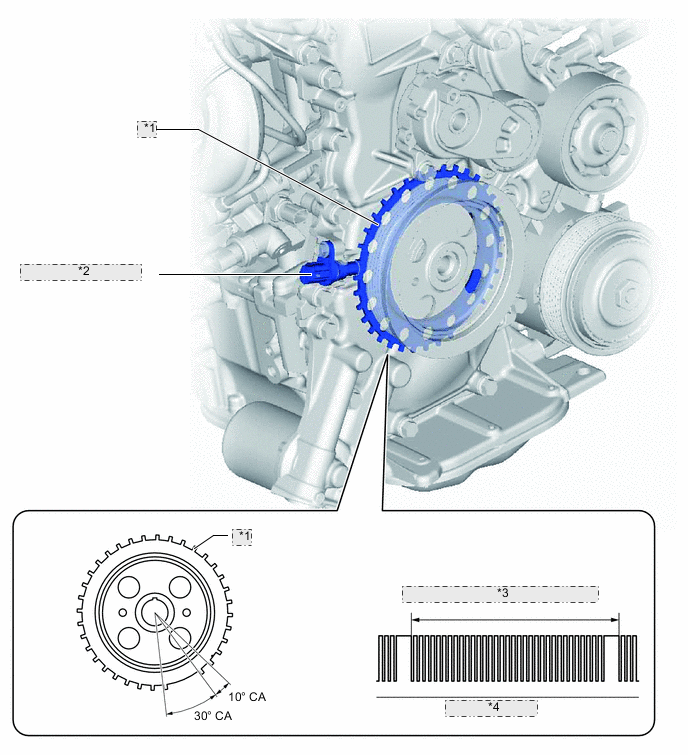
*1 Crank Angle Sensor Plate *2 Crank Position Sensor *3 Crank Angle Sensor Plate (360° CA) *4 Output Waveforms -
An MRE type crank position sensor consists of an MRE, a magnet and a sensor. The direction of the magnetic field changes due to the profile (protruding and non-protruding portions) of the crank angle sensor plate, which passes by the sensor. As a result, the resistance of the MRE changes, and the output voltage to the ECM changes to high or low. The ECM detects the crankshaft position based on this output voltage.
-
The differences between a MRE type sensor and the pick-up coil type sensor used on the conventional models are as follows:
-
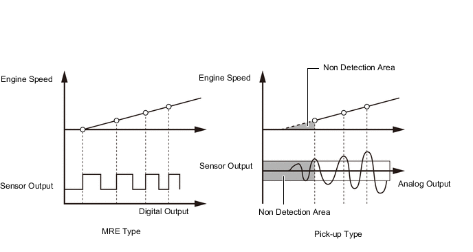
The MRE type sensor outputs a constant level of high and low digital signals regardless of the engine speed. Therefore, the MRE type sensor can detect the positions of the crankshaft at an early stage of cranking.
-
The pick-up coil type sensor outputs analog signals with levels that change with the engine speed.
Figure 1. MRE Type and Pick-up Coil Type Output Waveform Image Comparison
-
-
In order to deliver a smooth engine restart from the engine stop state, the MRE type crank position sensor provided on models with the stop and start system detects crankshaft movements swinging back and forth from the timing rotor rotation direction when the engine has been brought into a stop, helping the ECM determine a more exact crankshaft stop position.
-
The MRE type crank position sensor determines the timing rotor rotation direction from the phase difference between the 2 rectangular wave signals generated by the sensor itself, and then transmits Hi/Lo signals, a short low voltage time when the timing rotor rotates in the normal direction and a long low voltage time when in the reverse direction, to the ECM.
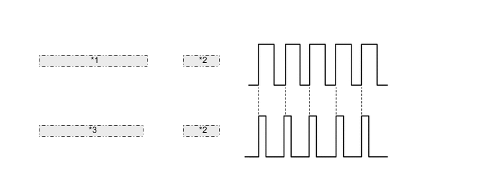
Sensor Output Waveforms *1 Normal Rotation Direction *2 Ne Signal *3 Reverse Rotation Direction
-