ENGINE UNIT
Info Added 2017-04-18 ![]()
-
CONSTRUCTION
-
The ventilation inside the stiffening crankcase assembly uses the same PCV valve (ventilation valve sub-assembly) as a Natural Aspiration (NA) engine. In addition, blowby gas ventilation control, which forcibly performs ventilation when in the supercharging range by using a ventilation ejector, is used. As a result, blowby gas with a hydrocarbons is prevented from being discharged into the atmosphere by forcibly introducing the blowby gas into the intake system and combusting the gas. Also, the same oil maintenance schedule as an NA engine is achieved by actively performing ventilation during all driving ranges.
-
As turbocharged engines produce more blowby gas than NA engines, an oil separate chamber is installed to the cylinder block sub-assembly to provide adequate length for the blowby gas passage. As a result, the efficiency of separating engine oil from the blowby gas is enhanced.
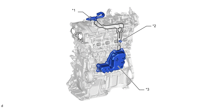
*1 Ventilation Ejector *2 PCV Valve (Ventilation Valve Sub-assembly) *3 Oil Separate Chamber - -
-
-
OPERATION
-
When operating in the turbocharged range, blowby gas is forcibly routed through the intake air duct by the ventilation ejector.
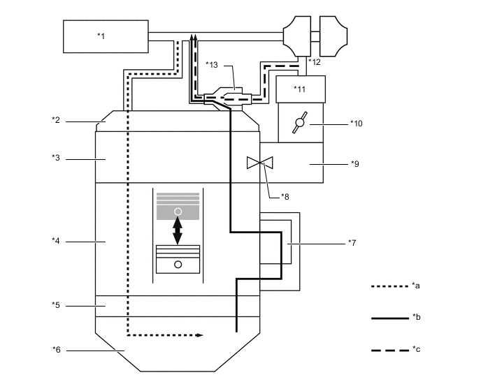
*1 Air Cleaner Assembly *2 Cylinder Head Cover Sub-assembly *3 Cylinder Head Sub-assembly *4 Cylinder Block Sub-assembly *5 Stiffening Crankcase Assembly *6 Oil Pan Sub-assembly *7 Oil Separate Chamber *8 PCV Valve (Ventilation Valve Sub-assembly) *9 Intake Manifold *10 Throttle Body with Motor Assembly *11 Intercooler Assembly *12 Turbocharger Sub-assembly *13 Ventilation Ejector - - *a Fresh Air *b Fresh Air + Blowby Gas *c Ejector Drive Gas - - -
When operating in the natural aspirated range, blowby gas is suctioned via the PCV valve (ventilation valve sub-assembly) due to the vacuum in the intake air ducts.
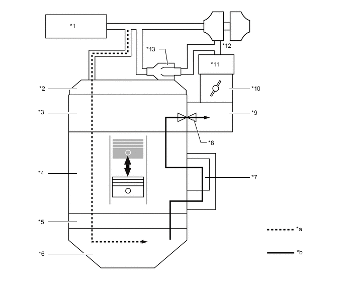
*1 Air Cleaner Assembly *2 Cylinder Head Cover Sub-assembly *3 Cylinder Head Sub-assembly *4 Cylinder Block Sub-assembly *5 Stiffening Crankcase Assembly *6 Oil Pan Sub-assembly *7 Oil Separate Chamber *8 PCV Valve (Ventilation Valve Sub-assembly) *9 Intake Manifold *10 Throttle Body with Motor Assembly *11 Intercooler Assembly *12 Turbocharger Sub-assembly *13 Ventilation Ejector - - *a Fresh Air *b Fresh Air + Blowby Gas -
The ventilation ejector uses the Venturi effect as its operating principle. Blowby gas is drawn in by introducing the high pressure air to the ventilation ejector.
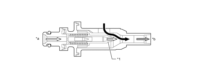
*1 Nozzle - - *a From Downstream of Turbocharger Sub-assembly *b Towards Upstream of Turbocharger Sub-assembly 
Blowby Gas 
Drive Gas 
Blowby Gas + Drive Gas - -
-