BODY STRUCTURE
-
CONSTRUCTION
-
Grille Shutter System
-
A grille shutter system is used. This system blocks the flow of air into the engine compartment from the lower radiator grille.
-
The grille shutter suitably controls cooling airflow for the engine and inverter by opening and closing the shutter, thus reducing drag.
-
-
Upper Body
-
The surface where the cowl top ventilator louver sub-assembly meets the windshield has been leveled off, and the shape around the front pillar and front door were smoothed to effectively reduce flow separation. As an additional measure to reduce flow separation, an optimized angle was adopted for the side surfaces of the front and rear bumper.
-
Rain gutter moldings have been added next to the windshield. The variation in height of the step between the windshield and front pillar has been reduced. Ample width has been ensured for the moldings to reduce airflow separation, thus achieving significant wind noise reduction.
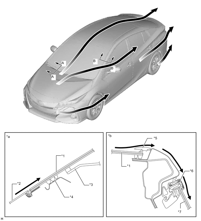
*1 Windshield *2 Cowl Top Ventilation Louver Sub-assembly *3 Instrument Panel *4 Cowl Top Panel *5 Rain Gutter Molding *6 Door Window Frame Molding *7 Front Door Glass - - *a A - A Cross Section *b B - B Cross Section -
The rear bumper corner shape for rectifying rearward airflow, and rear design for rectifying side and bottom airflow.

-
-
Aero Stabilizing Fin
-
An aero stabilizing fin are provided on the outer rear view mirror bases and rear combination lights for enhanced aerodynamics.
-
After passing the aero stabilizing fin, the air speed will increase and vortex flow will be generated.
-
This vortex increases the speed of surrounding air while at the same time pulling the airflow towards the vehicle body.
-
The airflow with higher speed passes near both sides of the vehicle body and ends at the rear of the vehicle. This helps to hold the vehicle body, thus stabilizing the vehicle.
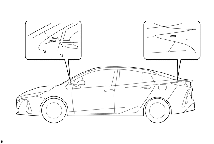
*a Aero Stabilizing Fin - -
-
-
-
Under Body
-
To create a smooth rearward airflow for the air which enters from the front to under floor, the following parts with airflow adjustment effects are located on the lower surface of the vehicle. Smooth airflow in the lower surface of the vehicle enhances the speed of airflow and a low pressure region is created between the vehicle and the road surface (Venturi effect). This low pressure region attracts the vehicle to the road surface, thus causing down force. Thus, superior straight-line stability has been achieved.
-
A flat airflow adjustment surface is provided for the engine under cover. Also, an aero stabilizing fin is provided.
-
The surface area of the engine under cover and floor covers has been increased, and the height from the ground has also been optimized. In addition, an aero stabilizing fin is provided.
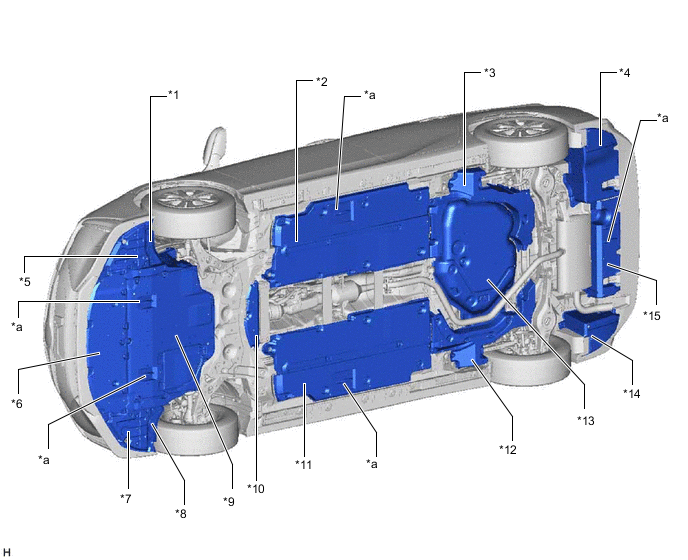
*1 Front Wheel Opening Extension LH *2 Front Floor Cover LH *3 Rear Floor Side Member Cover LH *4 No. 2 Floor Under Cover *5 Front Fender Splash Shield FR LH *6 No. 2 Engine Under Cover Assembly *7 Front Fender Splash Shield FR RH *8 Front Wheel Opening Extension RH *9 No. 1 Engine Under Cover Assembly *10 No. 2 Engine Under Cover *11 Front Floor Cover RH *12 Rear Floor Side Member Cover RH *13 No. 1 Floor Under Cover Assembly *14 No. 1 Floor Under Cover *15 Rear Body Floor Cover RR - - *a Aero Stabilizing Fin - - -
-
-