AIR CONDITIONING SYSTEM
-
FUNCTION OF MAIN COMPONENTS
Component Function Combination Meter Assembly
-
Multi-information Display
Allows operation and adjustment of the air conditioning system via switches. Air Conditioning Control Assembly Compressor with Motor Assembly Performs suction, compression and discharge of refrigerant gas. Blower Motor with Fan Sub-assembly Driven according to the target airflow volume calculated by the air conditioning amplifier assembly to blow air toward the cabin and circulate the air inside the cabin. Air Conditioning Amplifier Assembly Transmits and receives data to and from the switches and sensors, and controls the air conditioning system. Heat Pump ECU Assembly Receives the signals from the air conditioning amplifier assembly and sensors and controls cycle mode of air conditioning system. ECM Receives the signals from the engine coolant temperature sensor and transmits them to the air conditioning amplifier assembly. Hybrid Vehicle Control ECU Controls the compressor with motor assembly by signals from air conditioning amplifier assembly. Cooler (Room Temperature Sensor) Thermistor Assembly Detects the internal temperature inside the cabin and outputs that data to the air conditioning amplifier assembly. Ambient Temperature Sensor (Thermistor Assembly) Detects ambient temperature and outputs it to the air conditioning amplifier assembly. Rain Sensor Detects the glass temperature, glass surroundings temperature and glass humidity, and outputs them to the air conditioning amplifier assembly. Evaporator Temperature Sensor Detects the temperature of the cool air past the cooler evaporator sub-assembly and transmits the data to the air conditioning amplifier assembly. Automatic Light Control Sensor Detects the changes in the amount of solar energy and outputs them to the air conditioning amplifier assembly via the main body ECU (multiplex network body ECU). Air Conditioning Pressure Sensor Detects the refrigerant pressure and sends the data to the air conditioning amplifier assembly. Discharge Temperature Sensor Outputs a signal to the heat pump ECU assembly indicating the detected temperature of the high-temperature compressed refrigerant. Internal Condenser Temperature Sensor Outputs a signal to the heat pump ECU assembly indicating the detected temperature of the refrigerant after the internal condenser circuit. Heat Exchanger Temperature Sensor Outputs a signal to the heat pump ECU assembly indicating the detected temperature of the refrigerant after the outer heat exchanger circuit. Evaporator Pipe Temperature Sensor Outputs a signal to the heat pump ECU assembly indicating the detected temperature of the refrigerant after the No. 1 cooler evaporator sub-assembly circuit. No. 2 Air Conditioning Radiator Damper Servo Sub-assembly Damper Servo (Mode Switching) Controlled by the air conditioning amplifier assembly to move the mode control damper and switch the registers. Damper Servo Controlled by the air conditioning amplifier assembly to move the driver seat air mix control damper. No. 1 Blower Damper Servo Sub-assembly (Fresh/Recirculation Damper) Driven by the air conditioning amplifier assembly to move the fresh/recirculation damper. No. 1 Air Conditioning Radiator Damper Servo Sub-assembly (for Passenger Mode Switching) Controlled by the air conditioning amplifier assembly to move the mode control damper and switch the register. No. 3 Air Conditioning Radiator Damper Servo Sub-assembly (for Rear Mode Switching) Driven by the air conditioning amplifier assembly to move the rear mode control damper. Electric Expansion Valve (Cooling) Changes the rate of flow or flow direction of the refrigerant by changing the aperture of the expansion valve using the built-in stepping motor controlled by a signal from the heat pump ECU assembly. No. 1 Air Conditioning Accessory Assembly Electric Expansion Valve (Heating) Changes the rate of flow of the refrigerant by changing the aperture of the expansion valve using the built-in stepping motor controlled by a signal from the heat pump ECU assembly. Cyclone Separator Integrated Valve Is comprised of three parts (gas-liquid separator, magnet valve and differential pressure regulating valve). The differential pressure regulating valve opens to form a passage to separate gaseous and liquid refrigerant when the magnet valve is turned on based on signals from the heat pump ECU assembly. Low Pressure Magnetic Valve Changes the cycle mode by opening or closing the magnet valves based on signals from the heat pump ECU assembly. High Pressure Magnetic Valve -
-
SYSTEM CONTROL
-
Control List
Control Function Neural Network Control This control is capable of performing complex control by artificially simulating the information processing method of the nervous system of living organisms in order to establish a complex input/output relationship that is similar to a human brain. Heat Pump Air Conditioning Control In accordance with the target air outlet temperature calculated by the air conditioning amplifier assembly based on information from each sensor, the heat pump ECU assembly judges the cycle mode, and by opening or closing the magnet valve within the air conditioning circuit, switches the cycle mode. Outlet Air Temperature Control Based on the temperature set by the temperature control switch, the neural network control calculates the outlet air temperature based on the input signals from various sensors. The temperature setting for the driver and front passenger is controlled independently in order to provide a separate vehicle interior temperature for the right and left sides of the vehicle. Thus, air conditioning control that accommodates different occupant preferences has been achieved. When the seat heater of the driver or passenger seat is operating in HI mode, the heater outlet air temperature is controlled. Blower Control Controls the blower motor in accordance with the airflow volume that has been calculated by neural network control based on the input signals from various sensors. Automatically increases the blower level when the defroster is on. Air Outlet Control Automatically switches the air outlets in accordance with the outlet mode that has been calculated by neural network control based on the input signals from various sensors. In accordance with the engine coolant temperature, internal condenser estimated temperature, outside air temperature, amount of sunlight, required blower, outlet temperature and vehicle speed conditions, this control automatically switches the blower outlet to FOOT/DEF mode to prevent the windows from becoming fogged when the outside air temperature is low. Air Inlet Control Automatically controls the air inlet control damper to achieve the calculated outlet air temperature that is required. Drives the No. 1 blower damper servo sub-assembly (fresh/recirculation damper) in accordance with the operation of the air inlet control switch and moves the dampers to the FRESH or RECIRC position. Compressor Control During cooler cycle or series dehumidifying cycle
-
The air conditioning amplifier assembly calculates the target speed of the compressor based on the target evaporator temperature (which is calculated by the room temperature sensor, ambient temperature sensor and solar sensor) and the actual evaporator temperature that is detected by the evaporator temperature sensor in order to control the compressor speed.
During gas injection heat pump cycle, heater cycle or parallel dehumidifying cycle
-
The air conditioning amplifier assembly calculates the target speed of the compressor based on "the calculated heat pump ECU assembly internal condenser target temperature" and "internal condenser estimated temperature calculated based on temperature and pressure information" in order to control the compressor speed.
Turns the air conditioning on automatically when the AUTO button is pressed when the blower is on and the air conditioning is OFF. Decreases the compressor speed in order to ensure quietness when the vehicle is stopped. During heat pump cycle, even if the A/C switch is off, by driving the compressor with motor assembly, heating performance is ensured. Also, when the A/C switch is off, cooling, parallel dehumidifying and series dehumidifying are not performed. S-FLOW Control When the driver is the only passenger, the temperature setting, ambient temperature, cabin temperature and amount of sunlight are detected and an optimal amount of air conditioning is performed for the given conditions (only to driver side registers and front passenger side side register). Rear Window Defogger Control
-
Switches the rear defogger and outside rear view mirror heaters on for 15 minutes when the rear defogger and mirror heater switch is pressed.
-
Switches the rear defogger and outside rear view mirror heaters off if the button is pressed while they are operating
Outside Temperature Indication Control Based on the signals from the thermistor assembly, this control calculates the outside temperature, and this value is then corrected in the air conditioning amplifier, and shown on the multi-information display. ECO Drive Mode Control
-
When ECO drive mode is selected, the air conditioning amplifier assembly enters ECO air conditioning mode.
-
Pressing the ECO air conditioning mode switch cancels the ECO air conditioning mode.
Blower Customize During automatic air conditioning operation, the air volume can be adjusted in 3 levels using the air conditioning control assembly (AUTO FAST/ECO switch): NORMAL → ECO (small air volume) → FAST (large air volume). Dehumidifying Automatic Off Control Based on information from the rain sensor, automatically turns off dehumidifying when the air conditioning amplifier assembly judges that dehumidifying is unnecessary. Electric Power Control When the vehicle voltage is below the specified level, the air conditioning amplifier assembly saves the power source of some systems in accordance with the voltage signal from the hybrid vehicle control ECU. Diagnosis A Diagnostic Trouble Code (DTC) is stored in memory when the air conditioning amplifier assembly detects a problem in the air conditioning system. -
-
Neural Network Control
-
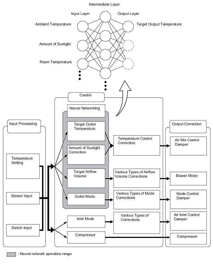
In the previous automatic air conditioning system, the air conditioning amplifier assembly determined the required outlet air temperature and blower air volume in accordance with a calculation formula that had been obtained based on information received from the sensors. However, because the senses of a person are rather complex, a given temperature is sensed differently depending on the environment in which the person is situated. For example, a given amount of solar radiation can feel comfortably warm in a cold climate, but extremely uncomfortable in a hot climate. Therefore, as a technique for performing a high level of control, a neural network is used in the automatic air conditioning system. With this technique, the data that has been collected under varying environmental conditions is stored in the air conditioning amplifier assembly, which effects control to provide enhanced air conditioning comfort.
-
The neural network control consists of neurons in an input layer, an intermediate layer, and an output layer. The input layer neurons process the input data of the ambient temperature, the amount of sunlight and the room temperature based on the signals of the switches and sensors, and output them to the intermediate layer neurons. Based on this data, the intermediate layer neurons adjust the strength of the links among the neurons. The sum of this data is then calculated by the output layer neurons in the form of the required outlet temperature, solar correction, target airflow volume and outlet mode control volume. Accordingly, the air conditioning amplifier assembly controls the servo motors and blower motor with fan sub-assembly in accordance with the control volumes that have been calculated by neural network control.
-
-
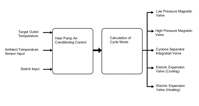
Heat Pump Air Conditioning Control
-
The operation type (cycle mode) of the heat pump air conditioning system includes the gas injection heat pump heater, heat pump heater, parallel dehumidifying, series dehumidifying, cooler, and outer heat exchanger defrosting.
-
Each cycle mode has the following functions (dehumidifying and heating).
Cycle Mode Function Dehumidifying Heating Heat Pump Heater 

Gas Injection Heat Pump Heater 
Parallel Dehumidifying Series Dehumidifying 
Cooler 
Tech Tips
The circle ○ indicates that the cycle mode uses the function, and the size of the circle ○ indicates its magnitude.
-
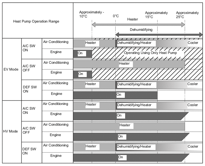
The cycle mode is determined based on each setting and the ambient temperature.
- EV Mode/HV Mode Operation
-
When the vehicle is in EV mode, air conditioning using the heat pump is performed when the ambient temperature is -10°C or more. Heating using the heat pump can be performed when the ambient temperature is between approximately -10°C and approximately 30°C. However, when the DEF switch is ON, the system operates based on the following:
-
When the vehicle is in HV mode, the engine is started as necessary to ensure a heat source.
- Operation when A/C Switch is on
-
When the A/C switch is on, dehumidifying or cooling is performed when the ambient temperature is 0°C or more.
-
When the vehicle is in EV mode, heating and dehumidifying can be operated simultaneously using the heat pump cycle (series dehumidifying or parallel dehumidifying).
-
When the vehicle is in HV mode, dehumidifying heating is performed by dehumidifying via the cooler and heating via the waste heat of the engine.
- Operation when DEF Switch is on
-
To clear condensation on the windshield glass, the engine is started as necessary to ensure a heat source. However, when the ambient temperature is approximately 15°C or more, the engine is not started when the vehicle is in EV mode as excessive heating performance is unnecessary.
Figure 1. Operation of Heat Pump and Engine ON Based on Request from Air Conditioning System
- Outer Heat Exchanger Defrosting
-
When there is history of the outer heat exchanger being frozen, the remote air conditioning system operates in defrosting mode. Heating starts when the outer heat exchanger is defrosted.
-
The heat pump ECU assembly determines the most appropriate operation type from the gas injection heat pump heater, heat pump heater, parallel dehumidifying, series dehumidifying, cooler and outer heat exchanger defrosting, and then operates each magnet valve to change the circuit.
-
The present valve opening amount of the electric expansion valve (cooling) and electric expansion valve (heating) is monitored by comparing the relative position. Furthermore, approximately 90 seconds after the power switch is turned off, the high pressure magnetic valve and low pressure magnetic valve turn off and the valve openings return to their original amounts when initialization control of the electric expansion valve (cooling) and electric expansion valve (heating) is performed.
Valve Position after Initialization Control Electric Expansion Valve (Heating) Cyclone Separator Integrated Valve Low Pressure Magnetic Valve High Pressure Magnetic Valve Electric Expansion Valve (Cooling) Partially Open Magnet Valve: Open
Differential Pressure Regulating Valve: Closed
Open Open Fully Closed
-
Gas Injection Heat Pump Heater
-
The heat pump cycle absorbs heat using the outer heat exchanger and releases heat using the internal condenser.
-
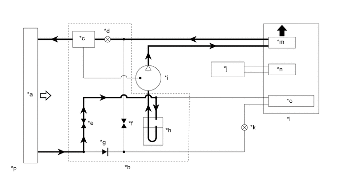
The refrigerant that is compressed using the compressor with motor assembly flows through the circuit of the internal condenser, electric expansion valve (heating), cyclone separator integrated valve, outer heat exchanger, low pressure magnetic valve, accumulator tank (receiver air conditioning tank), and part of the refrigerant directly returns to the compressor with motor assembly from the cyclone separator integrated valve.
-
Through this circuit, heating is performed by releasing heat using the internal condenser. The pressure of the liquid refrigerant is reduced and the liquid refrigerant is expands to a misty gas.
-
Misty refrigerant is separated within the cyclone separator integrated valve when the magnet valve is turned on. As the separated gaseous refrigerant directly flows back to the compressor with motor assembly, the amount of refrigerant in the compressor with motor assembly increases which increases the heating performance.
-
The liquid refrigerant separated by the cyclone separator integrated valve becomes a gaseous refrigerant by absorbing heat using the outer heat exchanger.
Gas Injection Heat Pump Heater Valve Position Electric Expansion Valve (Heating) Cyclone Separator Integrated Valve Low Pressure Magnetic Valve High Pressure Magnetic Valve Electric Expansion Valve (Cooling) Controlled Aperture Magnet Valve: Closed
Differential Pressure Regulating Valve: Open
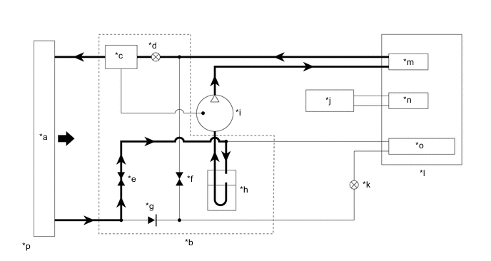
Open Closed Fully Closed Figure 2. Refrigerant Cycle of Gas Injection Heat Pump Heater
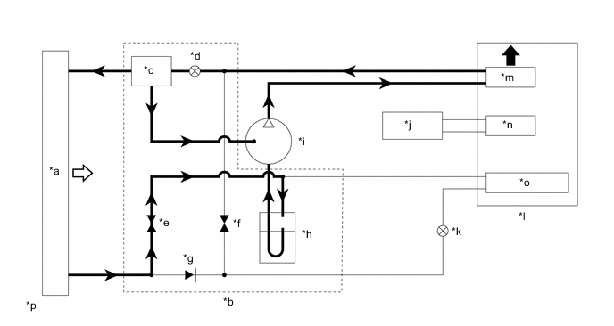
*a Outer Heat Exchanger (Cooler Condenser Assembly) *b Accumulator and Accessory Assembly *c Cyclone Separator Integrated Valve *d Electric Expansion Valve (Heating) *e Low Pressure Magnetic Valve *f High Pressure Magnetic Valve *g Check Valve *h Accumulator Tank (Receiver Air Conditioning Tank) *i Compressor with Motor Assembly *j Engine *k Electric Expansion Valve (Cooling) *l Air Conditioning Unit *m Internal Condenser *n Heater Radiator Unit Sub-assembly *o No. 1 Cooler Evaporator Sub-assembly *p The illustration shown is an example only. 
Radiation of Heat 
Absorption of Heat -
-
Heat Pump Heater
-
The heat pump cycle absorbs heat using the outer heat exchanger and releases heat using the internal condenser.
-
Refrigerant that is compressed by the compressor with motor assembly flows through the internal condenser --> electric expansion valve (heating) --> cyclone separator integrated valve --> outer heat exchanger --> low pressure magnetic valve --> accumulator tank (receiver air conditioning tank).
-
Through that circuit, heating is performed by releasing heat using the internal condenser and expanding the pressure reduced liquid refrigerant to a misty gas via the expansion valve to absorb heat in the outer heat exchanger.
Heat Pump Heater Valve Position Electric Expansion Valve (Heating) Cyclone Separator Integrated Valve Low Pressure Magnetic Valve High Pressure Magnetic Valve Electric Expansion Valve (Cooling) Controlled Aperture Magnet Valve: Open
Differential Pressure Regulating Valve: Closed
Open Closed Fully Closed Figure 3. Refrigerant Cycle of Heat Pump Heater
*a Outer Heat Exchanger (Cooler Condenser Assembly) *b Accumulator and Accessory Assembly *c Cyclone Separator Integrated Valve *d Electric Expansion Valve (Heating) *e Low Pressure Magnetic Valve *f High Pressure Magnetic Valve *g Check Valve *h Accumulator Tank (Receiver Air Conditioning Tank) *i Compressor with Motor Assembly *j Engine *k Electric Expansion Valve (Cooling) *l Air Conditioning Unit *m Internal Condenser *n Heater Radiator Unit Sub-assembly *o No. 1 Cooler Evaporator Sub-assembly *p The illustration shown is an example only. Radiation of Heat Absorption of Heat -
-
Parallel Dehumidifying
-
The heat pump cycle absorbs heat using the outer heat exchanger and No. 1 cooler evaporator sub-assembly and releases heat using the internal condenser.
-
Refrigerant that is compressed by the compressor with motor assembly flows through the internal condenser --> electric expansion valve (heating) --> cyclone separator integrated valve --> outer heat exchanger --> low pressure magnetic valve --> accumulator tank (receiver air conditioning tank) and in parallel through the internal condenser --> high pressure magnetic valve --> electric expansion valve (cooling) --> No. 1 cooler evaporator sub-assembly --> accumulator tank (receiver air conditioning tank).
-
Through that circuit, heating is performed by releasing heat using the internal condenser and expanding the pressure reduced liquid refrigerant to a misty gas via the expansion valve to absorb heat in the outer heat exchanger. Also, dehumidifying is performed by gaseous refrigerant using the electric expansion valve (cooling) to absorb heat in the No. 1 cooler evaporator sub-assembly.
-
To balance the refrigerant within the cycle, the opening amount of the electric expansion valve (heating) and electric expansion valve (cooling) are cooperatively controlled.
Parallel Dehumidifying Electric Expansion Valve (Heating) Cyclone Separator Integrated Valve Low Pressure Magnetic Valve High Pressure Magnetic Valve Electric Expansion Valve (Cooling) Controlled Aperture Magnet Valve: Open
Differential Pressure Regulating Valve: Closed
Open Open Controlled Aperture Figure 4. Refrigerant Cycle of Parallel Dehumidifying
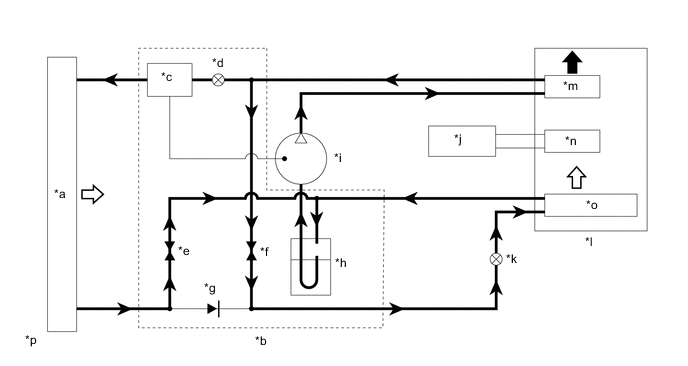
*a Outer Heat Exchanger (Cooler Condenser Assembly) *b Accumulator and Accessory Assembly *c Cyclone Separator Integrated Valve *d Electric Expansion Valve (Heating) *e Low Pressure Magnetic Valve *f High Pressure Magnetic Valve *g Check Valve *h Accumulator Tank (Receiver Air Conditioning Tank) *i Compressor with Motor Assembly *j Engine *k Electric Expansion Valve (Cooling) *l Air Conditioning Unit *m Internal Condenser *n Heater Radiator Unit Sub-assembly *o No. 1 Cooler Evaporator Sub-assembly *p The illustration shown is an example only. Radiation of Heat Absorption of Heat -
-
Series Dehumidifying
-
The heat pump cycle absorbs heat using the No. 1 cooler evaporator sub-assembly, releases heat using the internal condenser and releases heat or absorbs heat using the outer heat exchanger.
-
Refrigerant that is compressed by the compressor with motor assembly flows through the internal condenser --> electric expansion valve (heating) --> cyclone separator integrated valve --> outer heat exchanger --> check valve --> electric expansion valve (cooling) --> No. 1 cooler evaporator sub-assembly --> accumulator tank (receiver air conditioning tank).
-
Through this circuit, dehumidifying is performed by releasing heat using the internal condenser and expanding the pressure reduced liquid refrigerant to a misty gas via the expansion valve to release heat or absorb heat in the outer heat exchanger, and by gaseous refrigerant via the electric expansion valve (cooling) to absorb heat in the No. 1 cooler evaporator sub-assembly.
-
To balance the refrigerant within the cycle, the opening amount of the electric expansion valve (heating) and electric expansion valve (cooling) are cooperatively controlled.
Series Dehumidifying Valve Position Electric Expansion Valve (Heating) Cyclone Separator Integrated Valve Low Pressure Magnetic Valve High Pressure Magnetic Valve Electric Expansion Valve (Cooling) Controlled Aperture Magnet Valve: Open
Differential Pressure Regulating Valve: Closed
Closed Closed Controlled Aperture Figure 5. Refrigerant Cycle of Series Dehumidifying
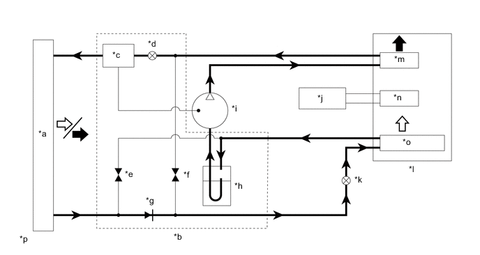
*a Outer Heat Exchanger (Cooler Condenser Assembly) *b Accumulator and Accessory Assembly *c Cyclone Separator Integrated Valve *d Electric Expansion Valve (Heating) *e Low Pressure Magnetic Valve *f High Pressure Magnetic Valve *g Check Valve *h Accumulator Tank (Receiver Air Conditioning Tank) *i Compressor with Motor Assembly *j Engine *k Electric Expansion Valve (Cooling) *l Air Conditioning Unit *m Internal Condenser *n Heater Radiator Unit Sub-assembly *o No. 1 Cooler Evaporator Sub-assembly *p The illustration shown is an example only. Radiation of Heat Absorption of Heat -
-
Cooler
-
The cooler cycle releases heat using the outer heat exchanger and absorbs heat using the No. 1 cooler evaporator sub-assembly.
-
Refrigerant that is compressed by the compressor with motor assembly flows through the internal condenser --> electric expansion valve (heating) --> cyclone separator integrated valve --> outer heat exchanger --> check valve --> electric expansion valve (cooling) --> No. 1 cooler evaporator sub-assembly --> accumulator tank (receiver air conditioning tank).
-
Through this circuit, dehumidifying is performed by releasing heat using the outer heat exchanger to liquidize the refrigerant, and by misting refrigerant via the electric expansion valve (cooling) to absorb heat using the No. 1 cooler evaporator sub-assembly.
Cooler Valve Position Electric Expansion Valve (Heating) Cyclone Separator Integrated Valve Low Pressure Magnetic Valve High Pressure Magnetic Valve Electric Expansion Valve (Cooling) Fully Open Magnet Valve: Open
Differential Pressure Regulating Valve: Closed
Closed Closed Controlled Aperture Figure 6. Refrigerant Cycle of Cooler
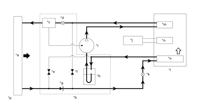
*a Outer Heat Exchanger (Cooler Condenser Assembly) *b Accumulator and Accessory Assembly *c Cyclone Separator Integrated Valve *d Electric Expansion Valve (Heating) *e Low Pressure Magnetic Valve *f High Pressure Magnetic Valve *g Check Valve *h Accumulator Tank (Receiver Air Conditioning Tank) *i Compressor with Motor Assembly *j Engine *k Electric Expansion Valve (Cooling) *l Air Conditioning Unit *m Internal Condenser *n Heater Radiator Unit Sub-assembly *o No. 1 Cooler Evaporator Sub-assembly *p The illustration shown is an example only. Radiation of Heat Absorption of Heat -
-
Outer Heat Exchanger Defrosting
-
When the heat pump air conditioning system is heating and the outer heat exchanger is absorbing heat from the outside air, frost may form on the surface of the outer heater exchanger when the outside temperature is low.
-
When using the vehicle, the temperature of the refrigerant is detected using the temperature sensor at the outlet of the outer heat exchanger, and if the air conditioning amplifier assembly judges that there is frost, the result is stored. When the remote air conditioning system is started and the judgment that there is frost has been memorized, the remote air conditioning system operates in outer heat exchanger defrosting mode.
-
During outer heat exchanger defrosting mode, the gaseous refrigerant that is compressed by the compressor with motor assembly enters the outer heat exchanger via the internal condenser, electric expansion valve (heating) and cyclone separator integrated valve and directly flows into the outer heat exchanger, and then the gaseous refrigerant defrosts the outer heat exchanger.
Outer Heat Exchanger Defrosting Valve Position Electric Expansion Valve (Heating) Cyclone Separator Integrated Valve Low Pressure Magnetic Valve High Pressure Magnetic Valve Electric Expansion Valve (Cooling) Controlled Aperture Magnet Valve: Open
Differential Pressure Regulating Valve: Closed
Open Closed Fully Closed Figure 7. Refrigerant Cycle of Outer Heat Exchanger Defrosting
*a Outer Heat Exchanger (Cooler Condenser Assembly) *b Accumulator and Accessory Assembly *c Cyclone Separator Integrated Valve *d Electric Expansion Valve (Heating) *e Low Pressure Magnetic Valve *f High Pressure Magnetic Valve *g Check Valve *h Accumulator Tank (Receiver Air Conditioning Tank) *i Compressor with Motor Assembly *j Engine *k Electric Expansion Valve (Cooling) *l Air Conditioning Unit *m Internal Condenser *n Heater Radiator Unit Sub-assembly *o No. 1 Cooler Evaporator Sub-assembly *p The illustration shown is an example only. Radiation of Heat - - -
-
-
S-FLOW Control
-
By using the occupant classification system and by detecting when the rear doors are opened and closed, the air conditioning amplifier assembly determines which seats are occupied and only blows air to the occupied seats.
-
-
ECO Air Conditioning Mode Control
-
In Eco air conditioning mode control, there are two types, the normal air conditioning mode, and Eco air conditioning mode, which gives fuel efficiency an even higher priority. Under specific conditions, the air conditioning amplifier assembly operates at a reduced level of air conditioning performance in order to improve fuel efficiency. Eco air conditioning mode can be selected by operating the Eco air conditioning switch.
Control Outline Inside/Outside Air Switch Control If the outside air temperature exceeds a certain limit, the mode switches to inside air recirculation. Blower Level Control In AUTO mode, the blower level is lowered to the specified value and control is performed. Also, when in warm-up control, the blower level decreases. Heater and Compressor Control The operation of the heater or the compressor with motor assembly is decreased, to a reserved operation level.
-
By pressing the Eco air conditioning mode switch, the air conditioning system can be turned on, but when the ECO drive mode switch in the pattern select switch assembly has been operated to set Eco drive mode, the air conditioning will also automatically enter Eco air conditioning mode control.
-
Pressing and holding the Eco air conditioning mode switch sets Eco air conditioning mode, and air conditioning control will be performed with fuel efficiency as an even higher priority (air conditioning will have more reserved operation).
-
If DEF mode is selected, air conditioning related Eco air conditioning mode control will be canceled in order to reduce fogging of the windows as quickly as possible. However, if DEF mode is canceled, Eco air conditioning mode control will be restored.
-
Pressing the Eco air conditioning mode switch again will cancel the Eco air conditioning mode control. Also, Eco air conditioning mode control may be canceled if another air conditioning system switch is operated, or if the power switch is turned OFF.
-
-
-
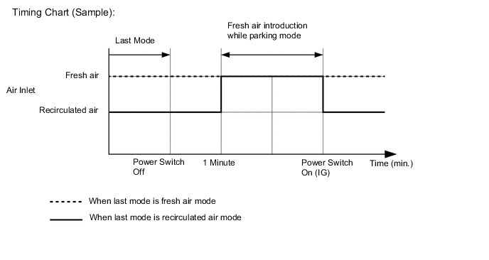
Fresh Air Introduction While Parking Control
-
While parking, fresh air introduction mode is automatically selected to enhance ventilation and reduce any odor remaining in the air conditioning unit, thus odor during hybrid system start-up is minimized.
-
-
-
DIAGNOSIS
-
The air conditioning amplifier assembly has a self-diagnosis function. It stores any operation malfunctions in the air conditioning system in memory in the form of Diagnostic Trouble Codes (DTCs). For details, refer to the Repair Manual.
-