AIR CONDITIONING SYSTEM
-
OUTLINE
-
The automatic air conditioning system uses left and right independent temperature control and neural network control to enhance comfort.
-
S-FLOW control is used to concentrate the air outlets on the front seats.
-
By utilizing a heat pump air conditioning system with gas injection function, an air conditioning system with a high efficiency ratio has been realized.
-
When outside temperatures are low, heating ability is ensured by not relying on engine coolant temperatures driving in EV mode.
-
Efficient heating of the vehicle contributes to enhanced EV mode distance.
-
-
By utilizing the remote air conditioning system remotely using the electrical key transmitter sub-assembly, the air conditioning system can be made to heat or cool the vehicle. With this, uncomfortable cabin temperatures (hot, cold) when entering the vehicle can be reduced.
-
It is possible to provide heating as well as cooling.
-
A dedicated power supply circuit for the remote air conditioning system is used.
-
-
When the charging timer system is operating, the climate prep function which uses the air conditioning system to heat or cool the air approximately 10 minutes prior to the set departure time can be utilized. With this, uncomfortable cabin temperatures (hot, cold) when entering the vehicle can be reduced.
-
-
SPECIFICATIONS
-
Ventilation and Heater Core
Component Specifications Heater Radiator Unit Sub-assembly Type Straight Flow Aluminum-II (SFA-II) Size (W x H x L) 222.3 mm x 120 mm x 27 mm (8.8 in. x 4.7 in. x 1.1 in.) Fin Pitch 1.8 mm (0.07 in.) Internal Condenser Type Global Inner-fin Condenser (GIC) Size (W x H x L) 222.6 mm x 120 mm x 11.5 mm (8.8 in. x 4.7 in. x 0.5 in.) Fin Pitch 1.5 mm (0.06 in.) Blower Motor with Fan Sub-assembly Motor Type DC Ferrite Brushless Fan Type Sirocco Fan Size (Dia. x H) Upper Side : 122.0 mm x 55.0 mm (4.8 in. x 2.2 in.)
Lower Side : 125.0 mm x 38 mm (4.9 in. x 1.5 in.)
-
Air Conditioning
Component Specifications Outer Heat Exchanger (Cooler Condenser Assembly) Type Multi-Flow (MF)-IV Size (W x H x L) 686 mm x 351 mm x 22 mm (27.0 in. x 13.8 in. x 0.9 in.) Fin Pitch 3.1 mm (0.1 in.) Compressor with Motor Assembly ESBG27 Refrigerant Type HFC-134a*1 HFO-1234yf*2 No. 1 Cooler Evaporator Sub-assembly Type Beneficial Refrigerant Stream (BRS) Size (W x H x L) 239.5 mm x 231 mm x 38 mm (9.4 in. x 9.1 in. x 1.5 in.) Fin Pitch 3.0 mm (0.1 in.) *1: Models using HFC-134a refrigerant
*2: Models using HFO-1234yf refrigerant
-
-
MAIN FEATURES
-
The air conditioning system has the following features:
Feature Outline High Performance
-
Neural network control is used, so passengers can finely control the air conditioning for maximum comfort.
-
A gas injection heat pump air conditioning system is utilized.
-
The remote air conditioning system is utilized.
-
A high efficiency type clean air filter, which has a pollen is used.
-
The blower control has 7 levels in manual mode and 31 levels in auto mode for more precise control.
Light Weight
-
A bus connector with a built-in communication/driver IC is used in a lightweight wire harness design to allow a reduced number of wires.
-
The use of this type of connector means that pulse pattern type servo motors can be used.
Compact
-
A blower motor with a built-in blower motor controller is used to achieve a compact construction.
-
The accumulator and accessory assembly combines the functional parts of the heat pump (accumulator tank, heating electric expansion valve, low pressure magnet valve, high pressure magnet valve, check valve and cyclone separator integrated valve) in a compact arrangement.
Others The following parts are used to ensure high cooling/heating performance while achieving a compact and lightweight construction:
-
Semi-center Location Air Conditioning Unit
-
ESBG27 Type Electric Inverter Compressor
-
Beneficial Refrigerant Stream (BRS) Evaporator
-
Straight Flow Aluminum (SFA)-II Heater Radiator Sub-assembly
-
Multi-Flow IV (MF-IV) Condenser (Outer Heat Exchanger)
-
Global Inner-fin Condenser (GIC) Condenser (Internal Condenser)
-
Electric Expansion Valve
-
Cyclone Separator Integrated Valve
-
-
Heat pump air conditioning system refrigeration cycle
-
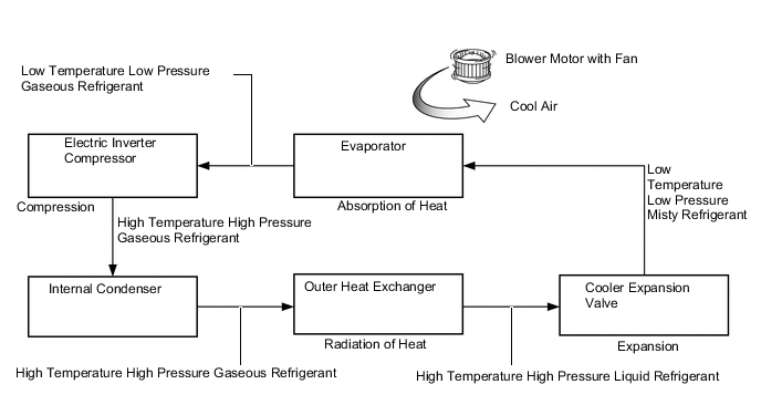
By using magnet valves to switch between the circuits of each unit, the heat pump air conditioning system operates a cooler cycle during cooling and a heat pump cycle during heating.
-
During the cooler cycle when cooling, refrigerant which is pumped through the outer heat exchanger by the electric inverter compressor at high-temperature and high-pressure, is expanded within the evaporator via the cooler expansion valve to provide cooling within the vehicle cabin.
Figure 1. Cooling
-
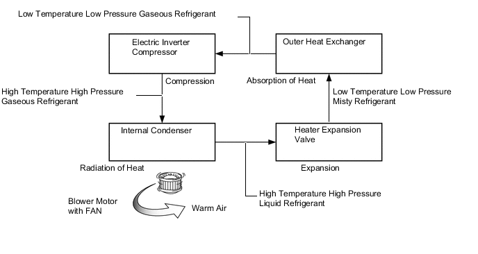
During the heat pump cycle when heating, by changing the circuit by operating magnet valves, refrigerant which is pumped through the internal condenser by the electric inverter compressor at high-temperature and high-pressure, is expanded within the outer heat exchanger via the heater expansion valve in order to absorb heat to provide heating within the vehicle cabin.
Figure 2. Heat Pump Heater
-
-
Gas Injection Heat Pump Heater
-
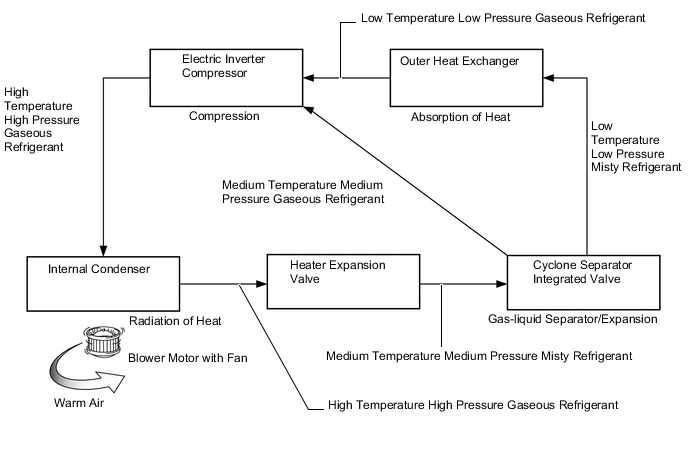
By using the gas injection heat pump, refrigerant which has released its heat is separated into liquid and gas by the cyclone separator integrated valve and the liquid refrigerant efficiently absorbs heat through the outer heat exchanger, and the quantity of refrigerant flow back to the gas injection equipped electric inverter compressor is increased. With this, when the outside temperature is low, heating performance is ensured.
-
-
-
PRECAUTION
-
Precaution for Refrigerant HFO-1234yf
-
Always use HFO-1234yf as the refrigerant.
CAUTION:
-
Do not charge the system with refrigerant near open flames, as HFO-1234yf is combustible.
-
When charging the system with refrigerant, make sure the area is well ventilated (especially be careful in areas where the gas can easily accumulate such as under lifts and in garage pits, as the gas is heavier than air).
-
Follow any local regulations regarding combustible gases.
-
Be sure to use a refrigerant recovery unit that is compatible with HFO-1234yf systems.
Tech Tips
The shape of the service port for refrigerant charging has an exclusive design conforming to international standards for HFO-1234yf to prevent improper refrigerant charging.
-
-
-
Compressor Oil
-
Always use ND-OIL 11 as the compressor oil.
-
When parts of the air conditioning system are removed, quickly block off any areas that are exposed to the outside air with plugs, vinyl tape, etc., as the oil used for HFO-1234yf systems absorbs moisture easily.
-
Do not allow the compressor oil to spray, as the oil used for HFO-1234yf systems has harmful effects on acrylic resins.
-
-
Remote Air Conditioning System
-
Do not use the remote air conditioning system when people are in the vehicle. If operation of the system is automatically suspended, the cabin temperature may become very hot or very cold.
-
The remote air conditioning system may not operate in the following situations.
-
The SOC of the HV battery assembly is low.
-
The ambient temperature is extremely low.
-
The temperature of the hybrid system is low.
-
-
When the remote air conditioning system is operating in defrost mode, because the performance of air conditioning system is restricted more than when operating in normal defrost mode, the windshield glass may remain foggy. Also, depending on the set temperature and temperature outside the vehicle, the exterior of the windshield glass may become foggy.
-
When the remote air conditioning system is operating in defrost mode and has just started operating, the effect of the heating may be limited due to the time required before heating begins.
-
-