SOLAR CHARGING SYSTEM
-
FUNCTION OF MAIN COMPONENTS
Component Function Solar Energy Control Unit Has 3 built-in DC-DC converters and supplies electricity generated by the solar roof (No. 1 roof window glass sub-assembly LH) to each electrical load. Solar Battery
-
Sends the battery temperature signal to the solar energy control unit.
-
Temporarily stores the solar generated power.
Solar Roof (No. 1 Roof Window Glass Sub-assembly LH) Generates power using the solar panel installed to the roof of the vehicle. Hybrid Vehicle Control ECU Judges whether charging of the HV battery assembly is possible and sends the signal to the solar energy control unit. Battery ECU Assembly
-
Monitors the HV battery assembly and sends a signal to the hybrid vehicle control ECU indicating that charging is possible.
-
Turns on the CHR (charger) relay.
Combination Meter Assembly Displays the total amount of power generated since the vehicle left the factory and a chart of the current power generation on the multi-information display. Certification ECU (Smart KeyECU Assembly) Wakes up the hybrid vehicle control ECU when charging the HV battery assembly after receiving a signal from the solar energy control unit. -
-
FUNCTION
-
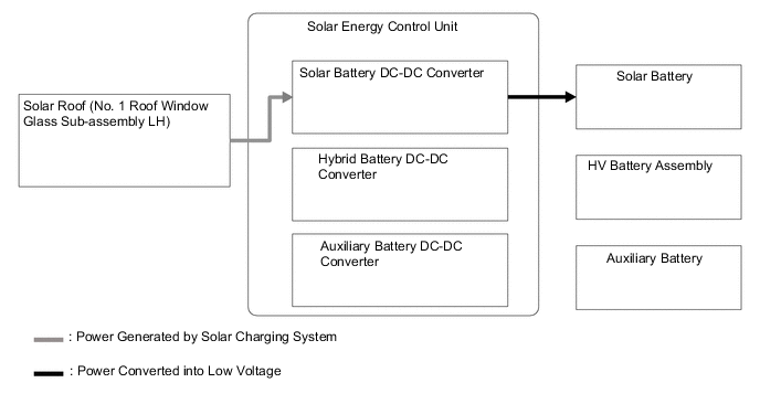
The solar charging system charges the solar battery and HV battery assembly or supplies power to the auxiliary battery system by increasing or decreasing the voltage generated by the solar roof (No. 1 roof window glass sub-assembly LH) using the DC-DC converter built into the solar energy control unit.
-
Depending on the state of the vehicle, the solar charging system changes the circuit to which it supplies power.
Operation Ignition Condition Vehicle Condition Distribution of Power Charging of Solar Battery Charging of HV Battery Assembly Supply to Auxiliary Power System Mode A IG OFF - ○ ○ ○ Mode B IG OFF Plug-in charging being performed ○*1 - - Battery heating system operating Air conditioning system operating in cooperation with timer charging function Remote climate control system operating ON (ACC) - ON (IG) - Mode C READY ON - ○*2 - ○ *1: Operation stops when the solar battery charge becomes sufficient (exceeds the SOC upper threshold).
*2: As this is a control to maintain the SOC of the solar battery at a certain level, charging stops before the battery is fully charged.
-
-
OPERATION
-
In mode A, the HV battery assembly is charged by repeating the following procedure:
Ignition Condition Vehicle Condition IG OFF -
-
Power generated by the solar roof (No. 1 roof window glass sub-assembly LH) that is increased or decreased in voltage by the solar battery DC-DC converter to charge the solar battery until it is sufficiently charged (SOC upper threshold).
If the power generation of the solar roof is low, the solar energy control unit stops the system.
After stopping the system, the solar energy control unit checks the generation of power by the solar roof every 15 minutes and starts the system if the power generation exceeds the threshold.
-
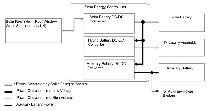
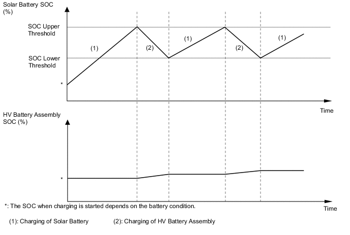
When the SOC of the solar battery becomes about 80%, power generated by the solar roof (No. 1 Roof Window Glass Sub-assembly LH) that was increased or decreased in voltage by the solar battery DC-DC converter to charge the solar battery is increased in voltage by the HV battery DC-DC converter to charge the HV battery assembly. When the SOC of the solar battery drops below the SOC lower threshold, charging of the HV battery assembly stops.
-
Change in Charging Status of Solar Battery and HV Battery
-
In the following situation, charging of the HV battery assembly is not performed.
-
The SOC of the HV battery assembly is 90% or more.
-
Temperature protection function of the solar charging system is operating.*
-
The cable is disconnected from the ausiliary battery negative (-) terminal.*
*: In this case, charging of the solar battery is also not performed.
-
-
-
In mode B, power that was generated by the solar roof (No. 1 roof window glass sub-assembly LH) is increased or decreased in voltage by the solar battery DC-DC converter to charge the solar battery until it is sufficiently charged (SOC upper threshold).
Ignition Condition Vehicle Condition IG OFF Plug-in charging being performed Battery heating system operating Air conditioning system operating in cooperation with timer charging function Remote climate control system operating ON (ACC) - ON (IG) -
-
In mode C, the following 2 operations are performed:
-
Power generated by the solar roof (No. 1 roof window glass sub-assembly LH) that was increased or decreased in voltage by the solar battery DC-DC converter is decreased in voltage by the auxiliary power DC-DC converter to supply power to the auxiliary battery system to decrease power consumption of the HV battery assembly.
-
Power that was generated by the solar roof (No. 1 roof window glass sub assembly LH) is increased or decreased in voltage by the solar battery DC-DC converter to maintain the SOC of the solar battery at a certain level.
Ignition Condition Vehicle Condition READY ON - 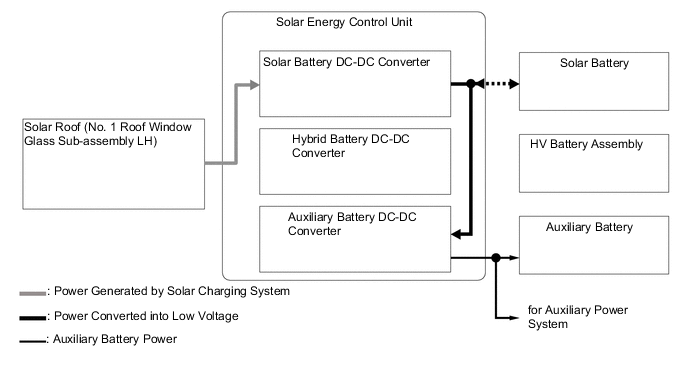
-
-