NAVIGATION SYSTEM / MULTI INFORMATION SYSTEM
-
FUNCTION OF MAIN COMPONENTS
Component Function Radio and Display Receiver Assembly*1
-
Receives operation signals from the panel switches and touch-sensitive display panel, which allows flick or drag operation, and data from various components positioned in different parts of the vehicle and sends them to the navigation ECU.
-
Processes navigation information and the operation status from the navigation ECU and displays them on the multi-display.
-
Receives audio signals such as voice guidance from the navigation ECU and sends them to the speaker.*2
-
Receives audio signals such as voice guidance from the navigation ECU and sends them to the stereo component amplifier assembly.*3
Major Components of Radio and Display Receiver Assembly*1 Multi-display Panel
-
Displays a map screen or an operation screen based on image signals from the navigation ECU.
-
Sends operation signals input via the touch-sensitive display panel to the navigation ECU.
Navigation ECU*1
-
Houses a navigation computer, gyro sensor and GPS receiver, and processes operation signals or vehicle status signals from the radio and display receiver assembly, controlling the navigation system.
-
Sends image and audio signals, such as navigation information, and the operation status to the radio and display receiver assembly.
Major Components of Navigation ECU*1 Navigation Computer
-
Corrects the vehicle position based on location information calculated from GPS information, vehicle speed signals, information from the built-in sensors and the shift status.
-
Applies the mark of the calculated vehicle position to the map data and sends the information and operation status to the radio and display receiver assembly.
-
Sends audio signals such as voice guidance provided in accordance with the vehicle position, to the radio and display receiver assembly.
Gyro Sensor Detects the vehicle's vertical axis rotation speed (yaw rate and rotation movement) and sends it to the navigation computer. GPS Receiver Demodulates GPS information received by the navigation antenna assembly, calculates the vehicle position and sends the position signal to the navigation computer. Navigation Receiver Assembly*4 Receives and processes data from the built-in components, such as the touch-sensitive display panel which allows flick or drag operation, navigation computer, gyro sensor or GPS receiver and various components positioned in different parts of the vehicle, controlling the navigation system and providing various information and the operation status via the multi-display using images, voice and sounds. Major Components of Navigation Receiver Assembly*4 Multi-display Panel
-
Displays a map screen or an operation screen based on image signals from the navigation computer.
-
Sends operation signals input via the touch-sensitive display panel to the navigation computer.
Navigation Computer
-
Updates the vehicle position based on location information calculated from GPS information, vehicle speed signals, information from the built-in sensors and the shift status.
-
Applies the mark of the calculated vehicle position to the map data in the microSD card (disc player disc) and sends the data to the multi-display.
-
Sends voice guidance audio signals to the stereo component amplifier assembly.
-
Sends navigation information, such as directions and route guidance, to the combination meter assembly or combination meter mirror ECU*5.
Gyro Sensor Detects the vehicle's vertical axis rotation speed (yaw rate and rotation movement) and sends it to the navigation computer. GPS Receiver Demodulates GPS information received by the navigation antenna assembly, calculates the vehicle position and sends the position signal to the navigation computer. microSD Card Slot Interfaces with the microSD card (disc player disc), which contains map data, the navigation system control program, etc. microSD Card (Disc Player Disc)*4 Contains map data and the navigation system control program, etc. Navigation Antenna Assembly Receives GPS signals from satellites in orbit around the Earth, at an altitude of approximately 20,200 km (12,600 miles), and sends them to the navigation ECU*1 or navigation receiver assembly*4. Parking Brake Switch Assembly Sends the parking brake position signal to the radio and display receiver assembly*1 or navigation receiver assembly*4. Hybrid Vehicle Control ECU Hybrid Vehicle Control ECU Sends an R shift position signal to the instrument panel junction block assembly. Instrument Panel Junction Block Assembly Instrument panel junction block assembly sends an R shift position signal to the radio and display receiver assembly*1 or navigation receiver assembly*4. Roof Antenna Assembly
-
AM
-
FM Main
-
Receives radio broadcasting signals (AM/FM main).
-
Amplifies radio broadcasting signals from the radio antenna and sends them to the radio and display receiver assembly*1 or navigation receiver assembly*4.
Window Glass Antenna Wire (Rear)
-
FM-sub
Receives radio broadcasting signals (FM-sub). No. 1 Amplifier Antenna Assembly Amplifies radio broadcasting signals from the radio antenna and sends them to the radio and display receiver assembly*1 or navigation receiver assembly*4. Window Glass Antenna Wire (Front)*6
-
DAB
Receives radio broadcasting signals (DAB). Digital Audio Broadcasting Antenna Assembly*6 Amplifies DAB signals from the DAB antenna and sends them to the radio and display receiver assembly. Steering Pad Switch Assembly Sends operation signals from switches such as the volume switch, mode switch, seek switch and voice switch, to the spiral cable with sensor sub-assembly. Spiral Cable with Sensor Sub-assembly Sends operation signals from the steering pad switch assembly to the radio and display receiver assembly*1 or navigation receiver assembly*4. Map Light Assembly Houses the telephone microphone. Telephone Microphone Assembly Recognizes speech during voice recognition system operation and sends the audio signal to the radio and display receiver assembly*1 or navigation receiver assembly*4. No. 1 Stereo Jack Adapter Assembly
-
Sends audio signal to the radio and display receiver assembly*1 or navigation receiver assembly*4 when an auxiliary device is connected.
-
Communicates with the radio and display receiver assembly*1 or navigation receiver assembly*4 via a USB communication line when a USB memory device, portable audio player (USB type) or Apple product is connected.
Combination Meter Assembly
-
Sends vehicle speed signals to the radio and display receiver assembly*1, navigation receiver assembly*4 or stereo component amplifier assembly*3.
-
Displays navigation information, such as directions and route guidance, sent from the navigation receiver assembly on the multi-information display.*4
Combination Meter Mirror ECU*5 Displays navigation information, such as directions and route guidance, sent from the navigation receiver assembly on the headup display.*4 Stereo Component Amplifier Assembly*3 Amplifies audio signals sent from the radio and display receiver assembly*1 or navigation receiver assembly*4 and sends them to the speakers. *1: Models for Europe
*2: Models with 6-speaker system
*3: Models with 10-speaker system
*4: Destination package for Taiwan
*5: Models with headup display
*6: Models with Digital Audio Broadcast (DAB) tuner
-
-
FUNCTION
-
Navigation Screen
-
The navigation computer calculates the present position and direction of travel, then determines a route and calculates the driving distance based on the following information sources:
-
Map data in the navigation ECU (Models for Europe)
-
Map data in the microSD card (disc player disc) (Destination package for Taiwan)
-
Global Positioning System (GPS) satellites
-
Built-in gyro sensor
-
Vehicle speed signal
-
Reverse signal
-
Parking brake signal
-
Radio Data System Traffic Message Channel (RDS-TMC) signal (Models for Europe)
-
Real-time Traffic Information (TMC) signal (Destination package for Taiwan)
Item Function Map Display Map Scroll Scroll operation on the map screen can be selected in the following 2 ways:
-
Flick/drag scrolling: Flick or drag in the direction that brings your desired location closer to the center of the map screen.
-
Point scrolling: Enables scrolling by connecting the touch points on the map screen.
Taillight-interlocked Map Color Change Changes the color of the map screen that is displayed when the taillights are turned on. North Up/Heading Up
-
If North Up is selected, regardless of the direction of vehicle travel, north is always up. If North Up is selected, regardless of the direction of vehicle travel, north is always up.
-
If Heading Up is selected, the direction of vehicle travel is always up.
3D Display Displays a 3-dimensional (3D) view of the map. 3D Icon Display*1 In some areas during the 3D display, buildings and landmarks are displayed using real image icons. Multi-step Scale Display Changes the map scale in 14 steps. Street Name Indication on Scrolled Map*1 Displays the street name and city name even when the map screen is being scrolled. Road Number Sign Board Display*1 Displays the road number on the map. Point of Interest Display Displays selected types of points of interest as marks on the map. Multiple Display Function*2 Displays different mode screens on a screen that is split into 3 views or 2 views. Route Guidance Demonstration Demonstrates the route guidance to the destination. Current Position Display Function Displays the latitude, longitude and altitude of the current position based on the GPS signals being received. Speed Limit Display*1 Displays the speed limit of the road currently being traveled on. Safety Camera Display*1 Displays safety camera icons on the map. Traffic Bar*1 A traffic message icon and traffic congestion information are displayed based on traffic information received via the internet. RDS-TMC Display*1 Displays RDS-TMC icons, arrows, pop-up messages and indicators when RDS-TMC service is being received. Traffic Information Display*2 Displays TMC icons, arrows and indicators when TMC service is being received. Destination Search Preset Destination Memory Search Sets a pre-registered point as a destination point while driving. Address Search A destination can be set by entering a country, and town name/code name, and street/intersection name.*1 A destination can be set by city/town name.*2 Point of Interest Search A destination can be set in 2 ways:*1
-
The name of a POI can be entered and then searched for after selecting a search area. Search areas include defined areas (such as a user selected country, state and city), near the current position, near the main destination, or along the current route.
-
A POI category can be selected and searched for near the current position, in a defined area (such as a user selected country, state and city), near the main destination, or along the current route.
A destination can be set in 3 ways:*2
-
Preset search
-
Category search
-
Name search
Destination List Search*2 Sets a destination from an item in the registered destination list. Online Search*1 Allows use of an internet search engine to set a destination using the most up to date information. Google Sync Search*1 Sets a destination searched for using street view or panoramio. Previous Destination Search A destination can be set using the destination list in which previously set destinations are stored. Map Search A destination can be set by using the cursor on the map screen. Route Search Multiple Destination Setting Sets multiple destinations. Can also rearrange sequence of the destinations. Multiple Route Search Searches for multiple routes. Search Condition Designation Searches for fast, short, and ecological routes.*1 Searches for the priority to time, etc.*2 Detour Search*1 Changes the route to detour around a section of the route. Adds Waypoints*2 Adds waypoints along with the set route to set the pass points. Regulated Road Consideration*1 Performs searches which consider regulated roads. Avoidance Area*2 Searches for a route that avoids a designated area. Avoid Traffic Search*1 Manually changes to another route to avoid heavy congestion. Auto Re-route Search*2 Performs automatic re-route search if the vehicle deviates from the set route. Guidance Voice Guidance Provides voice guidance about the distance and the direction of travel to a destination point based on road conditions and vehicle speed. Next Turn Guidance Next Turn Guidance Provides guidance about the distance to the next turn and indicates the direction of the turn using an arrow. Lane Information Guidance*2 Provides lane information and indicates the lane to be driven in when the vehicle is on a multiple lane road. Intersection Zoom-in Display*2 Zooms in and displays the intersection in 2D or 3D along with an arrow while driving in the vicinity of an intersection. Motorway (Highway) Exit or Junction Display*1 When the vehicle approaches an exit or junction, the motorway guidance screen will be displayed. Lane Recommendation Display*1 When the vehicle approaches a maneuver point, the lane recommendation will be displayed. Turn List Display*1 Displays a turn list on the right side of the 2-screen display. Distance-to-destination Display Displays the distance from the present location to the destination. Estimated Arrival Time Display Displays estimated arrival time. Others Voice Recognition*1 Recognizes pre-programmed system commands spoken to operate the navigation system. *1: Models for Europe
*2: Destination package for Taiwan
-
-
-
Setup Screen (Models for Europe)
-
The settings for the functions of the multi-display are available from the setup screen. The settings for the functions of the multi-display are available from the setup screen.
Item Function General Setting
-
The language can be selected.
-
The voice guidance volume, phone voice volume, ring volume and voice recognition dialog volume can be adjusted or switched off.
-
The unit of measurement for distance can be changed.
-
The unit of measurement for fuel consumption can be changed.
-
The beep sound can be set to on/off.
-
Automatic text scrolling can be turned off.
-
The capacitive touch button sensor sensitivity can be changed.
-
Data can be stored on a USB memory device.
-
Data can be copied from a USB memory device.
-
Registered information (personal data) can be cleared.
-
System information
-
Third party software information used in the multimedia system, such as notices, can be displayed.
Display Settings
-
Day mode can be set (the screen remains in day mode regardless of the position of the headlight switch).
-
The screen can be turned off.
-
The map menu, camera and video screen can be adjusted.
Audio Settings
-
Sound quality can be adjusted.
-
The level of the ASL (Automatic Sound Levelizer) can be adjusted.
-
The ASL (Automatic Sound Levelizer) can be turned on/off.
-
Surround sound can be turned on/off.*1
Connectivity Settings
-
Bluetooth system settings can be changed:
-
The Bluetooth function can be turned on/off
-
Connectable Bluetooth devices can be search
-
The names of the Bluetooth devices that are currently connected or that are in the connection history can be displayed in a list. Additionally, availability information for each Bluetooth device is displayed.
-
Cost warnings function and roaming warning function on/off setting
-
Change of the system name and PIN code used for certification while connecting via Bluetooth
-
Wi-Fi communication function settings can be displayed or changed:
-
The Wi-Fi communication function can be turned on/off
-
Display a list of available Wi-Fi networks and change the connection priority
-
Automatic connection to Wi-Fi networks on/off setting
-
Confirmation of connection to a Wi-Fi network message on/off setting
-
A profile for connecting to the internet can be set.
-
The connection method for automatically connecting to the internet can be set.
-
The following detailed Toyota web account settings can be displayed or changed:
-
Display of TOYOTA web account
-
Setting of new account or changing an existing account
-
Reception settings of remotely customized vehicle settings data from Toyota portal site
-
Upload settings of remotely customized vehicle settings data to TOYOTA portal site
Phone Settings
-
Message reception notification can be turned on or off.
-
E-mail reception notification can be turned on or off.
-
The ring tone can be changed or turned off.
-
Phone book data stored on a cellular phone can be transferred manually.
Vehicle Settings
-
Customizable vehicle settings can be changed.
-
Back camera guide line settings can be changed.*2
*1: Models with 10-speaker system
*2: Models with parking assist monitor system
-
-
-
Setup Screen (Destination Package for Taiwan)
-
The settings for the functions of the multi-display are available from the setup screen.
Tech Tips
The display order of the menu icons may vary depending on the country where the vehicle is sold.
Item Function General Settings
-
The unit of measurement for fuel consumption can be changed.
-
The beep sound can be set to on/off.
-
The color of the screen buttons can be changed.
-
Automatic return from the audio screen to the home screen after audio operation can be changed.
-
The capacitive touch button sensor sensitivity can be changed.
-
Animations can be set to on/off.
-
The opening image can be changed.
-
The screen off image can be changed.
-
Registered information (personal data) can be cleared.
-
The navigation system program can be updated.
-
Third party software information used in the navigation system, such as notices, can be displayed.
Home Screen Settings The display items/area on the home screen can be changed. Voice Settings The voice guidance volume can be adjusted or switched off. Display Settings
-
Map menu, camera and video screens can be adjusted.
-
Depending on the position of the headlight switch, the screen changes to day or night mode.
Bluetooth Settings
-
Bluetooth devices can be registered.
-
Bluetooth devices can be deleted.
-
Bluetooth devices can be connected.
-
Bluetooth devices can be edited.
-
Bluetooth system settings can be displayed or changed:
-
Automatic connection to a Bluetooth device
-
Bluetooth device name
-
Bluetooth device PIN-code
-
Bluetooth device address
-
Display of Bluetooth device connection status
-
Bluetooth device profile
Phone Settings
-
A Bluetooth phone can be registered or connected.
-
Phone sound settings can be changed:
-
Ring tone
-
Ring tone volume
-
In-call volume
-
Contact/Call history settings can be changed:
-
Automatic contact/history transfer function settings when a PBAP compatible Bluetooth phone is connected
-
Contacts update
-
Contacts Sorting
-
Favorites list registration
-
Contacts deletion from the favorites list
-
Contact image display
-
Call history deletion*
-
New contact addition to the contact list*
-
Contact list editing*
-
Contact deletion from the contact list*
-
Voice tags can be added, edited and deleted
-
Phone display settings can be changed:
-
Incoming call display
"Full Screen": The incoming call display screen is displayed and can be operated on the screen.
"Drop-Down": A message is displayed on the upper side of the screen and can only be operated via the steering wheel switches.
-
Display of the automatic contact/history transfer completion message
Audio Settings
-
FM radio settings can be changed:
-
Radio text display on/off settings
-
Cover art settings can be changed.
Vehicle Information
-
Customizable vehicle settings can be changed.
-
Back camera guide line settings can be changed.
Screen Off The screen can be turned off. *: PBAP non-compatible phone, or PBAP compatible phone with the automatic telephone number transfer function set to off.
-
-
-
Fuel Consumption Screen
-
The fuel consumption screen is displayed as illustrated below. This screen has the display functions listed below.
Figure 1. Models for Europe
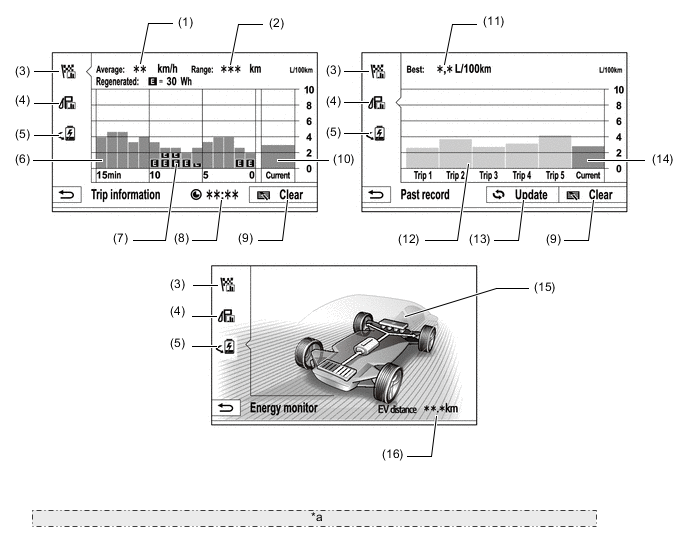
*a The illustrations are examples only. The illustrations may differ from the actual vehicle screens. Item Outline (1) Average Speed Displays an average speed value that has been calculated by the combination meter assembly, which is based on the distance driven and time elapsed since the power switch was turned on (IG). (2) Range Displays the approximate drivable distance. (3) Trip Information Switch Changes to the fuel consumption average per minute screen. (4) Past Record Switch Changes to the fuel consumption Past record (per trip) screen. (5) Energy Switch Changes the screen to the energy monitor screen. (6) Average Fuel Consumption Per Minute
-
Displays the value that has been calculated by the combination meter assembly, which is based on the driven distance and the volume of fuel consumed (fuel injection signal) since the ignition switch was turned to ON.
-
Displays the average fuel consumption for the last minute, or since clear was last selected.
(7) Recovered Energy
-
Indicates the recovered energy for 1 minute with "E" symbols.
-
The recovered energy status is calculated by the hybrid vehicle control ECU assembly.
(8) Elapsed Time Displays an elapsed time value that has been calculated by the combination meter assembly, which is based on the time elapsed since the power switch was turned on (IG). (9) Clear Switch Clears all past information. (10) Current Fuel Consumption Displays the instantaneous (current) fuel consumption value that has been calculated by the combination meter assembly, which is based on the driven distance and the volume of fuel consumed (fuel injection signal), since that the power switch was turned on (IG). (11) Best Fuel Consumption Displays the best (most economical) per trip fuel consumption. (12) Average Fuel Consumption Per Trip
-
Displays the current record and the last 5 average per trip fuel consumption records or the current record and those since clear was last selected.
-
Starts calculating the average fuel consumption when the average fuel consumption displayed on the combination meter assembly is reset.
(13) Update Switch
-
Restarts calculation of the average fuel consumption value.
-
Sends the average fuel consumption reset signal to the combination meter assembly to update the graph.
(14) Average Fuel Consumption Displays the average fuel consumption for this trip. (15) Energy Monitor Indicates the energy transmission direction, making it possible to confirm the current drive method (engine, motor or both), the power generation status by the engine and status of regenerative energy use.
-
The State Of Charge (SOC) of the battery can be checked on the meter. The meter shows the SOC in 8 levels.
-
Displays the energy monitor status that has been calculated by the hybrid vehicle control ECU.
(16) EV Distance Displays drivable distance for EV mode only in EV mode.* *: When using the air conditioning system, the drivable distance in EV mode may be different from the drivable distance displayed on the multi-information display of the combination meter assembly.
Figure 2. Destination Package for Taiwan
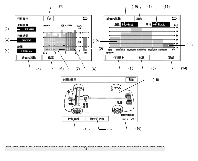
*a The illustrations are examples only. The illustrations may differ from the actual vehicle screens. Item Outline (1) Clear Switch Clears all past information. (2) Average Speed Displays an average speed value that has been calculated by the combination meter assembly, which is based on the distance driven and time elapsed since the power switch was turned on (IG). (3) Elapsed Time Displays an elapsed time value that has been calculated by the combination meter assembly, which is based on the time elapsed since the power switch was turned on (IG). (4) Range Displays the approximate drivable distance. (5) Past Record Switch Changes to the fuel consumption Past record (per trip) screen. (6) Energy Switch Changes the screen to the energy monitor screen. (7) Average Fuel Consumption Per Minute
-
Displays the value that has been calculated by the combination meter assembly, which is based on the driven distance and the volume of fuel consumed (fuel injection signal), since that the power switch was turned on (IG).
-
Displays the average fuel consumption for the last minute, or since clear was last selected.
(8) Recovered Energy
-
Indicates the recovered energy for 1 minute with "E" symbols.
-
The recovered energy status is calculated by the hybrid vehicle control ECU assembly.
(9) Current Fuel Consumption Displays the instantaneous (current) fuel consumption value that has been calculated by the combination meter assembly, which is based on the driven distance and the volume of fuel consumed (fuel injection signal), since that the power switch was turned on (IG). (10) Best Fuel Consumption Displays the best (most economical) per trip fuel consumption. (11) Average Fuel Consumption Displays the average fuel consumption for this trip. (12) Average Fuel Consumption Per Trip
-
Displays the current record and the last 5 average per trip fuel consumption records or the current record and those since clear was last selected.
-
Starts calculating the average fuel consumption when the average fuel consumption displayed on the combination meter assembly is reset.
(13) Trip Information Switch Changes to the fuel consumption average per minute screen. (14) Update Switch
-
Restarts calculation of the average fuel consumption value.
-
Sends the average fuel consumption reset signal to the combination meter assembly to update the graph.
(15) Energy Monitor Indicates the energy transmission direction, making it possible to confirm the current drive method (engine, motor or both), the power generation status by the engine and status of regenerative energy use.
-
The State Of Charge (SOC) of the battery can be checked on the meter. The meter shows the SOC in 8 levels.
-
Displays the energy monitor status that has been calculated by the hybrid vehicle control ECU.
(16) EV Distance Displays drivable distance for EV mode only in EV mode.* *: When using the air conditioning system, the drivable distance in EV mode may be different from the drivable distance displayed on the multi-information display of the combination meter assembly.
-
-
-
-
DIAGNOSIS
-
For details on the procedure required to enter the Service Menu screen, refer to the Repair Manual.
-