BRAKE CONTROL SYSTEM
-
CONSTRUCTION
-
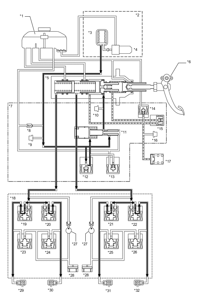
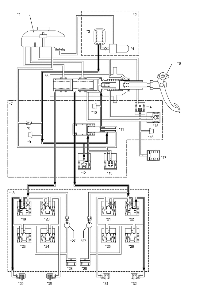
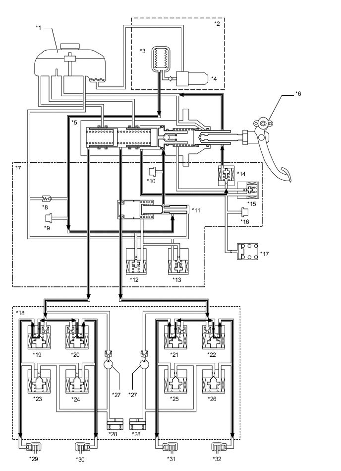
The brake control system consists of the linear solenoid valve (SLA, SLR), gap hold valve (SGH), stroke simulator cut valve (SSA), pressure holding solenoid valve (SFRH, SRLH, SRRH, SFLH), pressure reduction valve (SFRR, SRLR, SRRR, SFLR), etc., and controls the brake fluid pressure in each wheel cylinder.
Figure 1. Brake Fluid Circuit Diagram

*1 Brake Master Cylinder Reservoir Assembly *2 Brake Booster Pump Assembly *3 Accumulator *4 Pump Motor *5 Master Cylinder *6 Brake Pedal Stroke Sensor Assembly *7 Brake Actuator *8 Relief Valve *9 Accumulator Pressure Sensor (Pacc) *10 Servo Pressure Sensor (Psrv) *11 Regulator *12 Linear Solenoid Valve (SLA) *13 Linear Solenoid Valve (SLR) *14 Stroke Simulator Cut Valve (SSA) *15 Gap Hold Valve (SGH) *16 Stroke Simulator Pressure Sensor (Prct) *17 Stroke Simulator *18 Brake Actuator Assembly *19 Pressure Holding Solenoid Valve (SFRH) *20 Pressure Holding Solenoid Valve (SRLH) *21 Pressure Holding Solenoid Valve (SRRH) *22 Pressure Holding Solenoid Valve (SFLH) *23 Pressure Reduction Solenoid Valve (SFRR) *24 Pressure Reduction Solenoid Valve (SRLR) *25 Pressure Reduction Solenoid Valve (SRRR) *26 Pressure Reduction Solenoid Valve (SFLR) *27 Pump *28 Reservoir *29 Front Brake RH *30 Rear Brake LH *31 Rear Brake RH *32 Front Brake LH
-
-
OPERATION
-
During normal operation
-
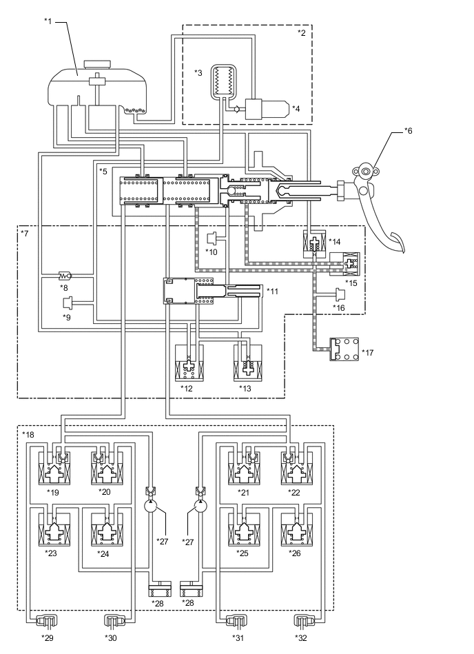
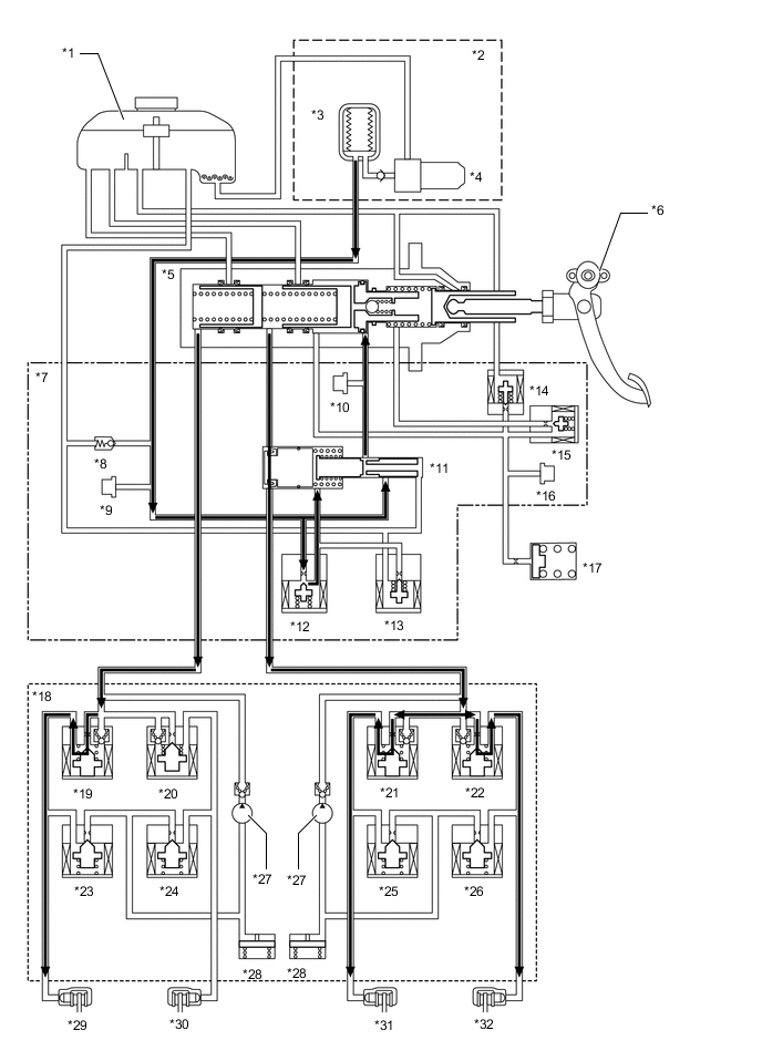
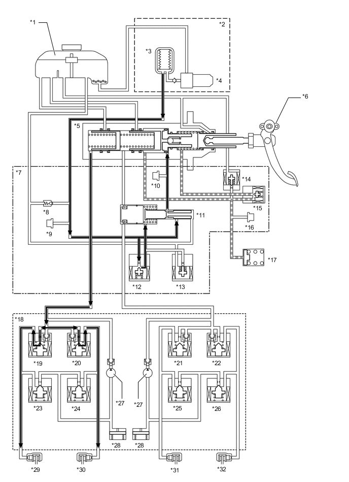
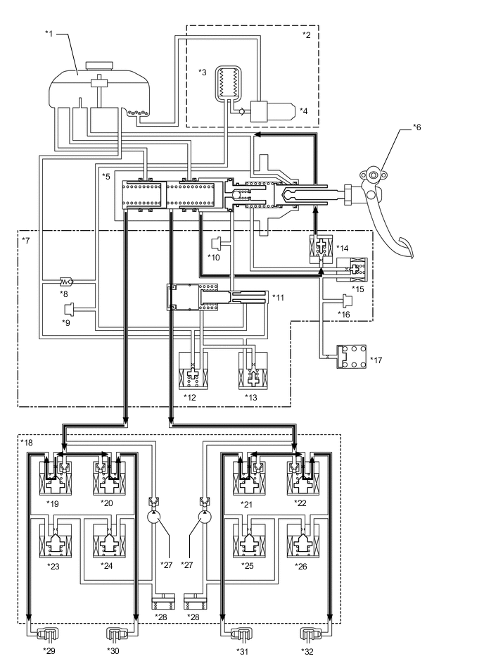
During normal braking, the stroke simulator cut valve (SSA) is closed and the gap hold valve (SGH) is open. The servo chamber pressure which is controlled by the linear solenoid valve according to the target wheel cylinder pressure is applied to the master cylinder chambers. By controlling the linear solenoid valves SLA and SLR, the brake fluid pressure of each wheel cylinder is increased, held or decreased.
Figure 2. Brake Fluid Diagram during Normal Operation (When Increasing Pressure)
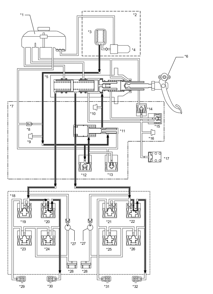
*1 Brake Master Cylinder Reservoir Assembly *2 Brake Booster Pump Assembly *3 Accumulator *4 Pump Motor *5 Master Cylinder *6 Brake Pedal Stroke Sensor Assembly *7 Brake Actuator *8 Relief Valve *9 Accumulator Pressure Sensor (Pacc) *10 Servo Pressure Sensor (Psrv) *11 Regulator *12 Linear Solenoid Valve (SLA) *13 Linear Solenoid Valve (SLR) *14 Stroke Simulator Cut Valve (SSA) *15 Gap Hold Valve (SGH) *16 Stroke Simulator Pressure Sensor (Prct) *17 Stroke Simulator *18 Brake Actuator Assembly *19 Pressure Holding Solenoid Valve (SFRH) *20 Pressure Holding Solenoid Valve (SRLH) *21 Pressure Holding Solenoid Valve (SRRH) *22 Pressure Holding Solenoid Valve (SFLH) *23 Pressure Reduction Solenoid Valve (SFRR) *24 Pressure Reduction Solenoid Valve (SRLR) *25 Pressure Reduction Solenoid Valve (SRRR) *26 Pressure Reduction Solenoid Valve (SFLR) *27 Pump *28 Reservoir *29 Front Brake RH *30 Rear Brake LH *31 Rear Brake RH *32 Front Brake LH Figure 3. Brake Fluid Circuit Diagram during Normal Operation (When Holding Pressure)
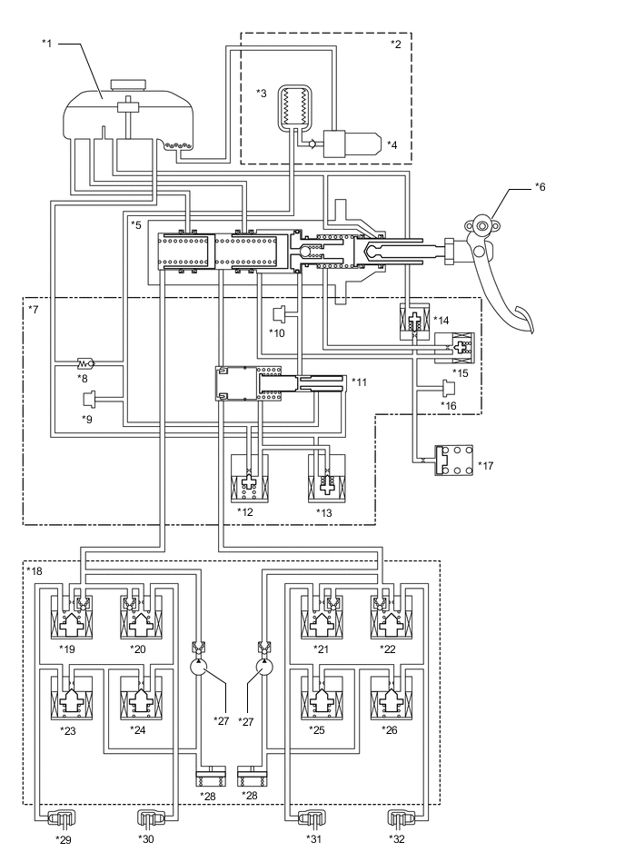
*1 Brake Master Cylinder Reservoir Assembly *2 Brake Booster Pump Assembly *3 Accumulator *4 Pump Motor *5 Master Cylinder *6 Brake Pedal Stroke Sensor Assembly *7 Brake Actuator *8 Relief Valve *9 Accumulator Pressure Sensor (Pacc) *10 Servo Pressure Sensor (Psrv) *11 Regulator *12 Linear Solenoid Valve (SLA) *13 Linear Solenoid Valve (SLR) *14 Stroke Simulator Cut Valve (SSA) *15 Gap Hold Valve (SGH) *16 Stroke Simulator Pressure Sensor (Prct) *17 Stroke Simulator *18 Brake Actuator Assembly *19 Pressure Holding Solenoid Valve (SFRH) *20 Pressure Holding Solenoid Valve (SRLH) *21 Pressure Holding Solenoid Valve (SRRH) *22 Pressure Holding Solenoid Valve (SFLH) *23 Pressure Reduction Solenoid Valve (SFRR) *24 Pressure Reduction Solenoid Valve (SRLR) *25 Pressure Reduction Solenoid Valve (SRRR) *26 Pressure Reduction Solenoid Valve (SFLR) *27 Pump *28 Reservoir *29 Front Brake RH *30 Rear Brake LH *31 Rear Brake RH *32 Front Brake LH Figure 4. Brake Fluid Circuit Diagram during Normal Operation (When Decreasing Pressure)
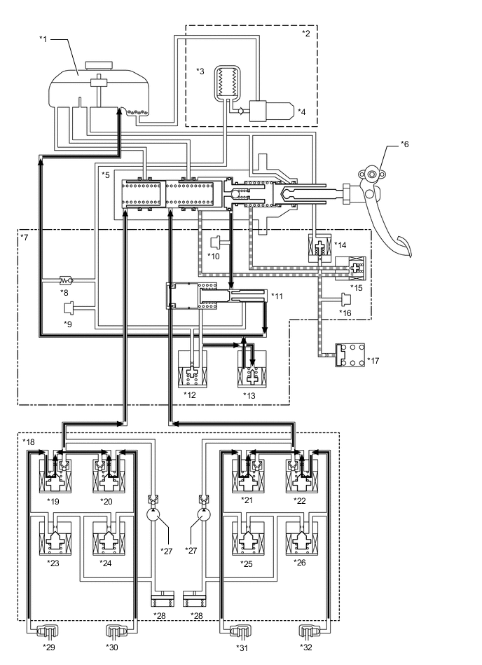
*1 Brake Master Cylinder Reservoir Assembly *2 Brake Booster Pump Assembly *3 Accumulator *4 Pump Motor *5 Master Cylinder *6 Brake Pedal Stroke Sensor Assembly *7 Brake Actuator *8 Relief Valve *9 Accumulator Pressure Sensor (Pacc) *10 Servo Pressure Sensor (Psrv) *11 Regulator *12 Linear Solenoid Valve (SLA) *13 Linear Solenoid Valve (SLR) *14 Stroke Simulator Cut Valve (SSA) *15 Gap Hold Valve (SGH) *16 Stroke Simulator Pressure Sensor (Prct) *17 Stroke Simulator *18 Brake Actuator Assembly *19 Pressure Holding Solenoid Valve (SFRH) *20 Pressure Holding Solenoid Valve (SRLH) *21 Pressure Holding Solenoid Valve (SRRH) *22 Pressure Holding Solenoid Valve (SFLH) *23 Pressure Reduction Solenoid Valve (SFRR) *24 Pressure Reduction Solenoid Valve (SRLR) *25 Pressure Reduction Solenoid Valve (SRRR) *26 Pressure Reduction Solenoid Valve (SFLR) *27 Pump *28 Reservoir *29 Front Brake RH *30 Rear Brake LH *31 Rear Brake RH *32 Front Brake LH Control Operation Normal Braking When Increasing Pressure When Holding Pressure When Decreasing Pressure Linear Solenoid Valve SLA ON (Open) OFF (Closed) OFF (Closed) SLR ON (Closed) ON (Closed) OFF (Open) Switching Solenoid Valve SSA ON (Closed) ON (Closed) ON (Closed) SGH ON (Open) ON (Open) ON (Open) Controlling Solenoid Valve SFRH OFF (Open) OFF (Open) OFF (Open) SRLH OFF (Open) OFF (Open) OFF (Open) SRRH OFF (Open) OFF (Open) OFF (Open) SFLH OFF (Open) OFF (Open) OFF (Open) SFRR OFF (Closed) OFF (Closed) OFF (Closed) SRLR OFF (Closed) OFF (Closed) OFF (Closed) SRRR OFF (Closed) OFF (Closed) OFF (Closed) SFLR OFF (Closed) OFF (Closed) OFF (Closed)
-
-
ABS with EBD operation
-
The ABS with EBD controls the pump, pressure holding solenoid valve and pressure reduction valve to control the brake fluid pressure of each wheel cylinder.
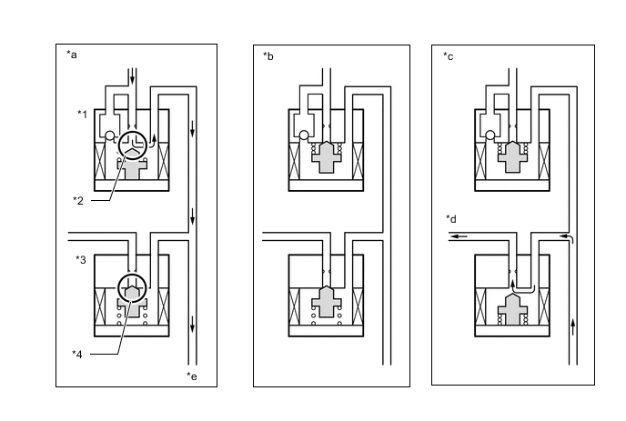
*1 Pressure Holding Solenoid Valve *2 Port 1 *3 Pressure Reduction Solenoid Valve *4 Port 2 *a Pressure Increase Mode *b Pressure Hold Mode *c Pressure Decrease Mode *d To Reservoir *e To Wheel Cylinder - - ABS with EBD Control Operation When Not Operating Normal Braking - - When Operating Pressure Increase Mode Pressure Hold Mode Pressure Decrease Mode Pressure Holding Solenoid Valve OFF ON ON Pressure Reduction Solenoid Valve OFF OFF ON Port 1 Open Closed Closed Port 2 Closed Closed Open Wheel Cylinder Pressure Apply Fluid Pressure Hold Fluid Pressure Release Fluid Pressure -
-
Brake Assist Operation
-
When brake assist control is operating, pressure is supplied from the brake booster pump assembly to the master cylinder chambers via the servo chamber to apply brake fluid pressure higher than that of the depression force of the brake pedal to each wheel cylinder.
Figure 5. Brake Assist Control Operation
*1 Brake Master Cylinder Reservoir Assembly *2 Brake Booster Pump Assembly *3 Accumulator *4 Pump Motor *5 Master Cylinder *6 Brake Pedal Stroke Sensor Assembly *7 Brake Actuator *8 Relief Valve *9 Accumulator Pressure Sensor (Pacc) *10 Servo Pressure Sensor (Psrv) *11 Regulator *12 Linear Solenoid Valve (SLA) *13 Linear Solenoid Valve (SLR) *14 Stroke Simulator Cut Valve (SSA) *15 Gap Hold Valve (SGH) *16 Stroke Simulator Pressure Sensor (Prct) *17 Stroke Simulator *18 Brake Actuator Assembly *19 Pressure Holding Solenoid Valve (SFRH) *20 Pressure Holding Solenoid Valve (SRLH) *21 Pressure Holding Solenoid Valve (SRRH) *22 Pressure Holding Solenoid Valve (SFLH) *23 Pressure Reduction Solenoid Valve (SFRR) *24 Pressure Reduction Solenoid Valve (SRLR) *25 Pressure Reduction Solenoid Valve (SRRR) *26 Pressure Reduction Solenoid Valve (SFLR) *27 Pump *28 Reservoir *29 Front Brake RH *30 Rear Brake LH *31 Rear Brake RH *32 Front Brake LH Brake Assist Control Operation When Brake Assist is not Operating When Brake Assist is Operating Linear Solenoid Valve SLA ON (Open) ON (Open) SLR ON (Closed) ON (Closed) Switching Solenoid Valve SSA ON (Closed) ON (Closed) SGH ON (Open) ON (Open) Controlling Solenoid Valve SFRH OFF (Open) OFF (Open) SRLH OFF (Open) OFF (Open) SRRH OFF (Open) OFF (Open) SFLH OFF (Open) OFF (Open) SFRR OFF (Closed) OFF (Closed) SRLR OFF (Closed) OFF (Closed) SRRR OFF (Closed) OFF (Closed) SFLR OFF (Closed) OFF (Closed)
-
-
TRC Operation
-
TRC pressurizes the master cylinder chambers due to servo pressure generated in the brake booster pump assembly, limits the drive force from the engine and controls each pressure holding solenoid valve and pressure reduction solenoid valve to apply more brake fluid pressure to the wheel cylinder of each drive wheel to reduce slippage.
-
The following illustration shows the operation during pressure increase mode.
Figure 6. TRC Control Operation
*1 Brake Master Cylinder Reservoir Assembly *2 Brake Booster Pump Assembly *3 Accumulator *4 Pump Motor *5 Master Cylinder *6 Brake Pedal Stroke Sensor Assembly *7 Brake Actuator *8 Relief Valve *9 Accumulator Pressure Sensor (Pacc) *10 Servo Pressure Sensor (Psrv) *11 Regulator *12 Linear Solenoid Valve (SLA) *13 Linear Solenoid Valve (SLR) *14 Stroke Simulator Cut Valve (SSA) *15 Gap Hold Valve (SGH) *16 Stroke Simulator Pressure Sensor (Prct) *17 Stroke Simulator *18 Brake Actuator Assembly *19 Pressure Holding Solenoid Valve (SFRH) *20 Pressure Holding Solenoid Valve (SRLH) *21 Pressure Holding Solenoid Valve (SRRH) *22 Pressure Holding Solenoid Valve (SFLH) *23 Pressure Reduction Solenoid Valve (SFRR) *24 Pressure Reduction Solenoid Valve (SRLR) *25 Pressure Reduction Solenoid Valve (SRRR) *26 Pressure Reduction Solenoid Valve (SFLR) *27 Pump *28 Reservoir *29 Front Brake RH *30 Rear Brake LH *31 Rear Brake RH *32 Front Brake LH TRC Control Operation TRC Not Operating TRC Operating Pressure Increase Mode Pressure Hold Mode Pressure Decrease Mode Linear Solenoid Valve SLA OFF (Closed) ON (Open) ON (Open) ON (Open) SLR OFF (Open) ON (Closed) ON (Closed) ON (Closed) Switching Solenoid Valve SSA ON (Closed) ON (Closed) ON (Closed) ON (Closed) SGH ON (Open) ON (Open) ON (Open) ON (Open) Controlling Solenoid Valve SFRH OFF (Open) OFF (Open) ON (Closed) ON (Closed) SRLH OFF (Open) ON (Closed) ON (Closed) ON (Closed) SRRH OFF (Open) ON (Closed) ON (Closed) ON (Closed) SFLH OFF (Open) OFF (Open) ON (Closed) ON (Closed) SFRR OFF (Closed) OFF (Closed) OFF (Closed) ON (Open) SRLR OFF (Closed) OFF (Closed) OFF (Closed) OFF (Closed) SRRR OFF (Closed) OFF (Closed) OFF (Closed) OFF (Closed) SFLR OFF (Closed) OFF (Closed) OFF (Closed) ON (Open)
-
-
VSC Operation
-
When the VSC system is operating, pressure is supplied from the brake booster pump assembly to the master cylinder chambers via the servo chamber to apply brake fluid pressure to each wheel cylinder to suppress front and rear wheel skidding.
-
Both of the following illustrations show the operation during pressure increase mode when the driver is not depressing the brake pedal while cornering to the right.
Figure 7. VSC Control Operation (During Understeer)
*1 Brake Master Cylinder Reservoir Assembly *2 Brake Booster Pump Assembly *3 Accumulator *4 Pump Motor *5 Master Cylinder *6 Brake Pedal Stroke Sensor Assembly *7 Brake Actuator *8 Relief Valve *9 Accumulator Pressure Sensor (Pacc) *10 Servo Pressure Sensor (Psrv) *11 Regulator *12 Linear Solenoid Valve (SLA) *13 Linear Solenoid Valve (SLR) *14 Stroke Simulator Cut Valve (SSA) *15 Gap Hold Valve (SGH) *16 Stroke Simulator Pressure Sensor (Prct) *17 Stroke Simulator *18 Brake Actuator Assembly *19 Pressure Holding Solenoid Valve (SFRH) *20 Pressure Holding Solenoid Valve (SRLH) *21 Pressure Holding Solenoid Valve (SRRH) *22 Pressure Holding Solenoid Valve (SFLH) *23 Pressure Reduction Solenoid Valve (SFRR) *24 Pressure Reduction Solenoid Valve (SRLR) *25 Pressure Reduction Solenoid Valve (SRRR) *26 Pressure Reduction Solenoid Valve (SFLR) *27 Pump *28 Reservoir *29 Front Brake RH *30 Rear Brake LH *31 Rear Brake RH *32 Front Brake LH VSC Control Operation (During Understeer) VSC Not Operating VSC Operating Pressure Increase Mode Pressure Hold Mode Pressure Decrease Mode Linear Solenoid Valve SLA OFF (Closed) ON (Open) ON (Open) ON (Open) SLR OFF (Open) ON (Closed) ON (Closed) ON (Closed) Switching Solenoid Valve SSA ON (Closed) ON (Closed) ON (Closed) ON (Closed) SGH ON (Open) ON (Open) ON (Open) ON (Open) Controlling Solenoid Valve SFRH OFF (Open) OFF (Open) ON (Closed) ON (Closed) SRLH OFF (Open) ON (Closed) ON (Closed) ON (Closed) SRRH OFF (Open) OFF (Open) ON (Closed) ON (Closed) SFLH OFF (Open) OFF (Open) ON (Closed) ON (Closed) SFRR OFF (Closed) OFF (Closed) OFF (Closed) ON (Open) SRLR OFF (Closed) OFF (Closed) OFF (Closed) OFF (Closed) SRRR OFF (Closed) OFF (Closed) OFF (Closed) ON (Open) SFLR OFF (Closed) OFF (Closed) OFF (Closed) ON (Open) Figure 8. VSC Control Operation (During Oversteer)
*1 Brake Master Cylinder Reservoir Assembly *2 Brake Booster Pump Assembly *3 Accumulator *4 Pump Motor *5 Master Cylinder *6 Brake Pedal Stroke Sensor Assembly *7 Brake Actuator *8 Relief Valve *9 Accumulator Pressure Sensor (Pacc) *10 Servo Pressure Sensor (Psrv) *11 Regulator *12 Linear Solenoid Valve (SLA) *13 Linear Solenoid Valve (SLR) *14 Stroke Simulator Cut Valve (SSA) *15 Gap Hold Valve (SGH) *16 Stroke Simulator Pressure Sensor (Prct) *17 Stroke Simulator *18 Brake Actuator Assembly *19 Pressure Holding Solenoid Valve (SFRH) *20 Pressure Holding Solenoid Valve (SRLH) *21 Pressure Holding Solenoid Valve (SRRH) *22 Pressure Holding Solenoid Valve (SFLH) *23 Pressure Reduction Solenoid Valve (SFRR) *24 Pressure Reduction Solenoid Valve (SRLR) *25 Pressure Reduction Solenoid Valve (SRRR) *26 Pressure Reduction Solenoid Valve (SFLR) *27 Pump *28 Reservoir *29 Front Brake RH *30 Rear Brake LH *31 Rear Brake RH *32 Front Brake LH VSC Control Operation (During Oversteer) VSC Not Operating VSC Operating Pressure Increase Mode Pressure Hold Mode Pressure Decrease Mode Linear Solenoid Valve SLA OFF (Closed) ON (Open) ON (Open) ON (Open) SLR OFF (Open) ON (Closed) ON (Closed) ON (Closed) Switching Solenoid Valve SSA ON (Closed) ON (Closed) ON (Closed) ON (Closed) SGH ON (Open) ON (Open) ON (Open) ON (Open) Controlling Solenoid Valve SFRH OFF (Open) ON (Closed) ON (Closed) ON (Closed) SRLH OFF (Open) OFF (Open) ON (Closed) ON (Closed) SRRH OFF (Open) ON (Closed) ON (Closed) ON (Closed) SFLH OFF (Open) OFF (Open) ON (Closed) ON (Closed) SFRR OFF (Closed) OFF (Closed) OFF (Closed) OFF (Closed) SRLR OFF (Closed) OFF (Closed) OFF (Closed) ON (Open) SRRR OFF (Closed) OFF (Closed) OFF (Closed) OFF (Closed) SFLR OFF (Closed) OFF (Closed) OFF (Closed) ON (Open)
-
-
Hill-assist Control Operation
-
After the driver operates the brakes, the pressure holding valve is closed to maintain a certain amount of the generated brake fluid pressure in each wheel cylinder to perform hill-start assist control.
-
The following illustration shows the operation during pressure hold mode.
Figure 9. Hill-assist Control Operation
*1 Brake Master Cylinder Reservoir Assembly *2 Brake Booster Pump Assembly *3 Accumulator *4 Pump Motor *5 Master Cylinder *6 Brake Pedal Stroke Sensor Assembly *7 Brake Actuator *8 Relief Valve *9 Accumulator Pressure Sensor (Pacc) *10 Servo Pressure Sensor (Psrv) *11 Regulator *12 Linear Solenoid Valve (SLA) *13 Linear Solenoid Valve (SLR) *14 Stroke Simulator Cut Valve (SSA) *15 Gap Hold Valve (SGH) *16 Stroke Simulator Pressure Sensor (Prct) *17 Stroke Simulator *18 Brake Actuator Assembly *19 Pressure Holding Solenoid Valve (SFRH) *20 Pressure Holding Solenoid Valve (SRLH) *21 Pressure Holding Solenoid Valve (SRRH) *22 Pressure Holding Solenoid Valve (SFLH) *23 Pressure Reduction Solenoid Valve (SFRR) *24 Pressure Reduction Solenoid Valve (SRLR) *25 Pressure Reduction Solenoid Valve (SRRR) *26 Pressure Reduction Solenoid Valve (SFLR) *27 Pump *28 Reservoir *29 Front Brake RH *30 Rear Brake LH *31 Rear Brake RH *32 Front Brake LH Hill-assist Control Operation Hill-assist Control Not Operating Hill-assist Control Operating When Holding Pressure When Decreasing Pressure Linear Solenoid Valve SLA OFF (Closed) OFF (Closed) OFF (Closed) SLR OFF (Open) ON (Closed) OFF (Open) Switching Solenoid Valve SSA ON (Closed) ON (Closed) ON (Closed) SGH ON (Open) ON (Open) ON (Open) Controlling Solenoid Valve SFRH OFF (Open) OFF (Open) OFF (Open) SRLH OFF (Open) OFF (Open) OFF (Open) SRRH OFF (Open) OFF (Open) OFF (Open) SFLH OFF (Open) OFF (Open) OFF (Open) SFRR OFF (Closed) OFF (Closed) OFF (Closed) SRLR OFF (Closed) OFF (Closed) OFF (Closed) SRRR OFF (Closed) OFF (Closed) OFF (Closed) SFLR OFF (Closed) OFF (Closed) OFF (Closed)
-
-
Dynamic radar cruise control brake operation
-
When dynamic radar cruise is performing brake control, pressure is supplied from the brake booster pump assembly to the master cylinder chambers via the servo chamber to apply the brake fluid pressure required for dynamic radar cruise control to each wheel cylinder.
-
Brake control of the dynamic radar cruise control system is that same as that for normal braking.
-
-
Pre-crash safety system operation
-
When pre-crash brake assist or pre-crash brake is performing brake control, pressure is supplied from the brake booster pump assembly to the master cylinder chambers via the servo chamber to apply the brake fluid pressure required for pre-crash brake assist or pre-crash brake to each wheel cylinder.
-
Brake control of the pre-crash brake assist and pre-crash brake are the same as that for normal braking.
-
-
Hydraulic booster mode operation (Operation when the brake actuator stops)
-
When the brake actuator stops due to failure, the stroke simulator cut valve (SSA) is opened and the gap hold valve (SGH) is closed. This applies the fluid pressure generated in the master cylinder chambers to each wheel cylinder.
Figure 10. Hydraulic Booster Mode Control Operation
*1 Brake Master Cylinder Reservoir Assembly *2 Brake Booster Pump Assembly *3 Accumulator *4 Pump Motor *5 Master Cylinder *6 Brake Pedal Stroke Sensor Assembly *7 Brake Actuator *8 Relief Valve *9 Accumulator Pressure Sensor (Pacc) *10 Servo Pressure Sensor (Psrv) *11 Regulator *12 Linear Solenoid Valve (SLA) *13 Linear Solenoid Valve (SLR) *14 Stroke Simulator Cut Valve (SSA) *15 Gap Hold Valve (SGH) *16 Stroke Simulator Pressure Sensor (Prct) *17 Stroke Simulator *18 Brake Actuator Assembly *19 Pressure Holding Solenoid Valve (SFRH) *20 Pressure Holding Solenoid Valve (SRLH) *21 Pressure Holding Solenoid Valve (SRRH) *22 Pressure Holding Solenoid Valve (SFLH) *23 Pressure Reduction Solenoid Valve (SFRR) *24 Pressure Reduction Solenoid Valve (SRLR) *25 Pressure Reduction Solenoid Valve (SRRR) *26 Pressure Reduction Solenoid Valve (SFLR) *27 Pump *28 Reservoir *29 Front Brake RH *30 Rear Brake LH *31 Rear Brake RH *32 Front Brake LH Hydraulic Booster Mode Control Operation Hydraulic Booster Mode Operating Linear Solenoid Valve SLA OFF (Closed) SLR OFF (Open) Switching Solenoid Valve SSA OFF (Open) SGH OFF (Closed) Controlling Solenoid Valve SFRH OFF (Open) SRLH OFF (Open) SRRH OFF (Open) SFLH OFF (Open) SFRR OFF (Closed) SRLR OFF (Closed) SRRR OFF (Closed) SFLR OFF (Closed)
-
-
Operation when one circuit is malfunctioning
-
The stroke simulator cut valve (SSA) is closed and gap hold valve (SGH) is opened. Pressure is supplied from the brake booster pump assembly to the master cylinder chambers via the servo chamber to apply the brake fluid pressure to each normal wheel cylinder to provide braking in one circuit.
-
The following illustration shows the operation during pressure increase mode.
Figure 11. Control Operation During One Circuit Malfunction
*1 Brake Master Cylinder Reservoir Assembly *2 Brake Booster Pump Assembly *3 Accumulator *4 Pump Motor *5 Master Cylinder *6 Brake Pedal Stroke Sensor Assembly *7 Brake Actuator *8 Relief Valve *9 Accumulator Pressure Sensor (Pacc) *10 Servo Pressure Sensor (Psrv) *11 Regulator *12 Linear Solenoid Valve (SLA) *13 Linear Solenoid Valve (SLR) *14 Stroke Simulator Cut Valve (SSA) *15 Gap Hold Valve (SGH) *16 Stroke Simulator Pressure Sensor (Prct) *17 Stroke Simulator *18 Brake Actuator Assembly *19 Pressure Holding Solenoid Valve (SFRH) *20 Pressure Holding Solenoid Valve (SRLH) *21 Pressure Holding Solenoid Valve (SRRH) *22 Pressure Holding Solenoid Valve (SFLH) *23 Pressure Reduction Solenoid Valve (SFRR) *24 Pressure Reduction Solenoid Valve (SRLR) *25 Pressure Reduction Solenoid Valve (SRRR) *26 Pressure Reduction Solenoid Valve (SFLR) *27 Pump *28 Reservoir *29 Front Brake RH *30 Rear Brake LH *31 Rear Brake RH *32 Front Brake LH Control Operation During One Circuit Malfunction Control Operation During One Circuit Malfunction When Increasing Pressure When Holding Pressure When Decreasing Pressure Linear Solenoid Valve SLA ON (Open) OFF (Closed) OFF (Closed) SLR ON (Closed) ON (Closed) OFF (Open) Switching Solenoid Valve SSA ON (Closed) ON (Closed) ON (Closed) SGH ON (Open) ON (Open) ON (Open) Controlling Solenoid Valve SFRH OFF (Open) OFF (Open) OFF (Open) SRLH OFF (Open) OFF (Open) OFF (Open) SRRH OFF (Open) OFF (Open) OFF (Open) SFLH OFF (Open) OFF (Open) OFF (Open) SFRR OFF (Closed) OFF (Closed) OFF (Closed) SRLR OFF (Closed) OFF (Closed) OFF (Closed) SRRR OFF (Closed) OFF (Closed) OFF (Closed) SFLR OFF (Closed) OFF (Closed) OFF (Closed)
-
-
Operation during power supply malfunction
-
The stroke simulator cut valve (SSA) is opened and gap hold valve (SGH) is closed. With this, pressure generated in the master cylinder chambers by the depression of the brake pedal by the driver is applied to each wheel cylinder.
Figure 12. Control Operation during Power Supply Malfunction
*1 Brake Master Cylinder Reservoir Assembly *2 Brake Booster Pump Assembly *3 Accumulator *4 Pump Motor *5 Master Cylinder *6 Brake Pedal Stroke Sensor Assembly *7 Brake Actuator *8 Relief Valve *9 Accumulator Pressure Sensor (Pacc) *10 Servo Pressure Sensor (Psrv) *11 Regulator *12 Linear Solenoid Valve (SLA) *13 Linear Solenoid Valve (SLR) *14 Stroke Simulator Cut Valve (SSA) *15 Gap Hold Valve (SGH) *16 Stroke Simulator Pressure Sensor (Prct) *17 Stroke Simulator *18 Brake Actuator Assembly *19 Pressure Holding Solenoid Valve (SFRH) *20 Pressure Holding Solenoid Valve (SRLH) *21 Pressure Holding Solenoid Valve (SRRH) *22 Pressure Holding Solenoid Valve (SFLH) *23 Pressure Reduction Solenoid Valve (SFRR) *24 Pressure Reduction Solenoid Valve (SRLR) *25 Pressure Reduction Solenoid Valve (SRRR) *26 Pressure Reduction Solenoid Valve (SFLR) *27 Pump *28 Reservoir *29 Front Brake RH *30 Rear Brake LH *31 Rear Brake RH *32 Front Brake LH Control Operation during Power Supply Malfunction Control Operation during Power Supply Malfunction Linear Solenoid Valve SLA OFF (Closed) SLR OFF (Open) Switching Solenoid Valve SSA OFF (Open) SGH OFF (Closed) Controlling Solenoid Valve SFRH OFF (Open) SRLH OFF (Open) SRRH OFF (Open) SFLH OFF (Open) SFRR OFF (Closed) SRLR OFF (Closed) SRRR OFF (Closed) SFLR OFF (Closed)
-
-