ELECTRONIC SHIFT LEVER SYSTEM
-
CONSTRUCTION
-
The parking lock actuator (shift control actuator assembly) consists of a switched reluctance motor and a cycloid reduction mechanism.
-
The parking lock actuator (shift control actuator assembly) is mounted on the side of the transaxle. Upon receiving an actuation signal from the hybrid vehicle control ECU, the motor rotates to engage or disengage the parking lock mechanism. As a result, the transaxle is locked or unlocked mechanically.
-
The switched reluctance motor is mainly composed of coil, stator, rotor and rotation angle sensor, and brushes and magnets are not used.
-
The rotation angle sensor consists of 2 Hall ICs. The 2 of them, called phases A and B, are used to detect the rotation angle of motor.
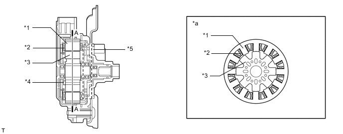
*1 Stator *2 Coil *3 Rotor *4 Rotation Angle Sensor *5 Cycloid Reduction Mechanism - - *a A-A Cross Section - - -
This motor rotates to lock or unlock parking. The hybrid vehicle control ECU detects the present shift position (parking locked or unlocked) in accordance with the rotation angle signal, which detects the extent of rotation of the motor.
-
The hybrid vehicle control ECU detects the direction of the motor rotation, the extent of the rotation, and its moving range through the combination of the pulses and the counting of the 2 Hall ICs with staggered phases (A phase and B phase), which are located in the rotation angle sensor. Once the moving range is detected, it is stored in the hybrid vehicle control ECU memory. However, it will be deleted if a battery terminal is disconnected.
Count Timing Pulse Changes A Phase B Phase Lock → Unlock OFF → OFF OFF → ON OFF → ON ON → ON ON → ON ON → OFF ON → OFF OFF → OFF Unlock → Lock OFF → ON OFF → OFF ON → ON OFF → ON ON → OFF ON → ON OFF → OFF ON → OFF 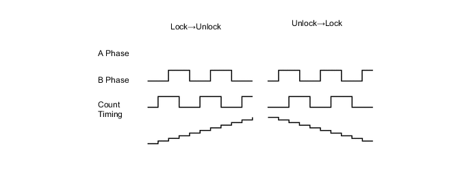
-
The parking lock position and unlock position, which provide the values to establish control criteria, are detected and stored in memory at the time the hybrid vehicle control ECU is started or the battery is reconnected. Initially, the hybrid vehicle control ECU causes the motor to rotate to the position that engages the lock, in order to store the parking lock position in memory. When the shift state is park (P) and a shift state other than park (P) is selected, the hybrid vehicle control ECU causes the motor to rotate in reverse, in order to store the unlock position in memory. However, if the hybrid vehicle control ECU has stored the moving range of the previous operation in its memory, it detects one of the present positions, and calculates the other position from the moving range stored in memory. These processes make it unnecessary for the system to be initialized after the actuator or the hybrid vehicle control ECU is replaced or the battery terminal is reconnected.
-
The cycloid reduction mechanism ensures the complete releasing operation of the parking lock when the vehicle is parked on a sloping road in which requires a high torque, since it amplifies the torque of the motor output shaft.
-
This mechanism consists of an eccentric plate that is mounted on the motor output shaft, an inside gear (61 teeth) that is secured to the housing, an outside gear (60 teeth), and an output shaft that rotates in unison with the outside gear.
-
Along with the rotational movement of the eccentric plate, which rotates in unison with the motor output shaft, the inside gear pushes against the outside gear while meshing. The outside gear, which has 1 tooth less than the inside gear, rotates 1 tooth less per rotation of the eccentric plate. As a result, the output shaft, which rotates in unison with the outside gear, outputs the rotational movement of the motor at a reduction ratio of 60.
Figure 1. Image of Cycloid Reduction Mechanism
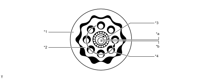
*1 Inside Gear *2 Outside Gear *3 Eccentric Plate *4 Output Shaft *a Eccentric Plate Center *b Motor Input Shaft Center 
Rotation Direction - -
-