ELECTRONIC SHIFT LEVER SYSTEM
-
FUNCTION OF MAIN COMPONENTS
-
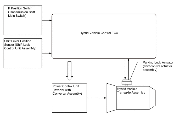
The main components of the electronic shift lever system have the following functions:
Component Function Shift Lever (Shift Lock Control Unit Assembly) Shift Lever Position Sensor Detects the shift positions (Home position, reverse (R), neutral (N), drive (D) or brake (B), and transmits the shift positions to the hybrid vehicle control ECU. P Position Switch (Transmission Shift Main Switch) As this switch turns on, it detects the driver's operation of the parking lock, and sends it to the hybrid vehicle control ECU. P Position Indicator Light Comes on when the parking lock is engaged, and comes off when the parking lock is disengaged. Parking Lock Actuator (Shift Control Actuator Assembly) Engages or disengages the transaxle parking lock mechanism. Hybrid Vehicle Control ECU
-
Controls MG1, MG2 and the engine in accordance with each shift state and performs shift control based on signals from the shift lever position sensor, P position switch (transmission shift main switch) and various ECUs.
-
Receives the gearshift control lock/unlock signal from the ID code box, and activates/deactivates the gearshift control lock.
Certification ECU (Smart Key ECU Assembly) Verifies the ID code output from the key. ID Code Box (Immobiliser Code ECU) Compares the ID code. Combination Meter Assembly Shift Position Indicator Illuminates the shift position indicator, which the driver has selected, in accordance with the shift state signals from the hybrid vehicle control ECU. Buzzer Sounds to alert the driver when the reject function is activated. Multi-information Display
-
Displays a warning message to alert the driver in accordance with a signal provided by the hybrid vehicle control ECU.
-
The master warning light may illuminate depending on the message displayed on the multi-information display.
-
-
-
SYSTEM CONTROL
-
Shift Control
-
The hybrid vehicle control ECU controls MG1, MG2 and the engine in accordance with each shift state based on signals such as the shift position signals (Home position, reverse (R), neutral (N), drive (D) or brake (B) from the shift lever position sensor and the switch on signals from the P position switch (transmission shift main switch).
-
The hybrid vehicle control ECU drives the parking lock actuator (shift control actuator assembly) based on the P position switch (transmission shift main switch) operation signal, shift lever operation signal, vehicle condition, etc. to engage or disengage the parking lock mechanism.
-
When the vehicle is being driven under normal conditions, the shift state can be changed to all states, provided that the reject function has not been tripped.
-
When the power switch is turned off with the vehicle stopped, the shift state is automatically changed to park (P).
-
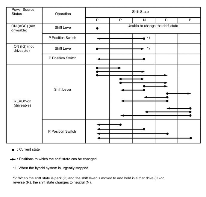
The table below shows how the shift lever operation and the P position switch operation are controlled at each shift state.
-
While the vehicle is being driven at a certain speed or more, the shift state can be changed to neutral (N) without having to hold the shift lever in neutral (N) for a certain amount of time. In this case, the buzzer in the combination meter assembly sounds (once), the master warning light blinks and a confirmation message is displayed on the multi-information display.
-
-
-
FUNCTION
-
Reject Function
-
To ensure safety, this system might not change the shift state even if the driver operates the shift lever or P position switch. In this case, it sounds a reject buzzer and changes the shift state as shown in the following table.
Reject Function Operation Conditions and Displayed Notifications Shift Operation which Causes Reject Function to Operate Shift State After Rejection Multi-information Display The driver attempts to perform a shift operation when the auxiliary battery voltage is insufficient. Current shift state is maintained Shifting Unavailable
Low 12-Volt Battery
See Owner's Manual
The driver attempts to change shift state repeatedly between park (P) and another state within a short period of time. Held in P state Shifting Unavailable
Wait a Moment and
Try Again
The driver attempts to change the shift state from park (P) to brake (B). Held in P state Unable to Shift to [B]
Vehicle Must be in [D]
to Shift to [B]
The driver attempts to change the shift state from neutral (N) to brake (B). Held in N state Unable to Shift to [B]
Vehicle Must be in [D]
to Shift to [B]
The driver attempts to change the shift state to drive (D), reverse (R) or brake (B) when the power switch is on (IG) and the ready indicator is not illuminated. Held in P state Unable to Shift to
[D], [B] and [R]
Shift after
Hybrid System READY
The driver attempts to change the shift state out of park (P) without depressing the brake pedal. Held in P state Shifting Unavailable
Press Brake to Shift
The driver attempts to change the shift state from reverse (R) to brake (B). Changed to N state Shifted to [N]
Vehicle Must Be in [D]
to Shift to [B]
The driver attempts to change the shift state from reverse (R) to drive (D) while moving backward. Changed to N state Shifted to [N]
Stop Vehicle to
Shift to [D]
The driver attempts to change the shift state from drive (D) to reverse (R) while moving forward. Changed to N state Shifted to [N]
Stop Vehicle to
Shift to [R]
The driver attempts to change the shift state to park (P) with the P position switch operation while the vehicle is moving. Changed to N state Shifted to [N]
Stop Vehicle to
Shift to [P]
The driver attempts to change the shift state out of park (P) while depressing both accelerator and brake pedal at the same time. Held in P state Shifting Unavailable
Release Accelerator and
Press Brake to Shift
The shift lever is not held in neutral (N) for a sufficient amount of time. Current shift state is maintained Shift to [N] by
Holding Shift Lever
in [N] Position
The driver attempts to change the shift state out of park (P) while the ready indicator is blinking. Held in P state Shifting Unavailable
While READY
Indicator is Flashing
Try Again
The driver attempts to change the shift state out of park (P) while the HV battery is being charged. Held in P state Shifting Unavailable
Disconnect Charge
Port Coupler
-
-
Shift Position Indicator
-
The shift lever is designed to always return to its home position. Therefore, the shift state that is currently selected can be checked on the shift position indicator, which is provided in the combination meter assembly.
-
In this system, brake (B) state operates in the engine brake range. Therefore, changing to brake (B) from a state other than drive (D) is prohibited. Accordingly, if the shift state is in a state other than drive (D) or brake (B), the B position indicator will turn off to prevent the driver from inadvertently changing to brake (B).
Figure 1. LHD Models
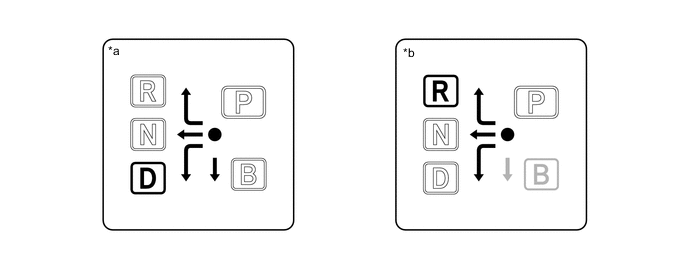
*a Displayed when the shift state is in drive (D). *b Displayed when the shift state is in reverse (R). Figure 2. RHD Models
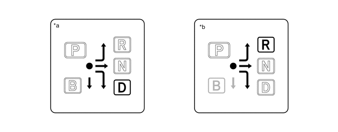
*a Displayed when the shift state is in drive (D). *b Displayed when the shift state is in reverse (R).
-
-
Shift related components malfunction display
-
When shift related components are malfunctioning, the buzzer inside the combination meter assembly sounds (once) and the master warning light illuminates. Also, a warning message and the action to be taken is displayed on the multi-information display to inform the driver.
Shift Related Component Malfunction Displayed Notifications Multi-information Display Function Constraint or Action to be Taken Low 12-Volt Battery
Apply Parking Brake
Securely While Parking
See Owner's Manual
-
The parking lock mechanism may not operate.
-
The hybrid system may not be able to be started.
-
Even if turning the power switch off, the power switch may change to on (ACC). In this situation, applying the parking brake may enable the power switch to be turned off.
-
Even after charging the auxiliary battery, the message may be displayed until the shift state is changed from park (P) to a shift state other than park (P).
Shift System Malfunction
Stop in a Safe Place
See Owner's Manual
The shift state may not change.
Stop the vehicle in a safe place.
[P] Switch Malfunction
Apply Parking Brake
Securely While Parking
See Owner's Manual
Even if the P position switch (transmission shift main switch) is pressed, the shift state may not change to park (P).
When parking, stop the vehicle on a level surface and make sure to apply the parking brake.
Shift System Malfunction
Apply Parking Brake
Securely While Parking
See Owner's Manual
The function that automatically changes the shift state to park (P) may not operate.
Before turning the power switch off, make sure to press the P position switch (transmission shift main switch) and confirm that the shift state park (P) is selected using the shift position indicator.
Shift System Malfunction
Apply Parking Brake
Securely While Parking
See Owner's Manual
-
The parking lock mechanism may not operate. When parking, stop the vehicle on a level surface and make sure to apply the parking brake.
-
The hybrid system may not be able to be started.
-
Even if turning the power switch off, the power switch may change to on (ACC). In this situation, applying the parking brake may enable the power switch to be turned off.
Shift System Malfunction
See Owner's Manual
If ignored, the system will not operate correctly and damage or a dangerous situation may occur unexpectedly. Shift System Malfunction
Shifting Unavailable
See Owner's Manual
The shift state may not change from park (P) to a shift state other than park (P). Shift System Not Active
Apply Parking Brake
Securely While Parking
See Owner's Manual
-
The parking lock mechanism may not operate. When parking, stop the vehicle on a level surface and make sure to apply the parking brake.
-
The hybrid system may not be able to be started.
-
Even if turning the power switch off, the power switch may change to on (ACC). In this situation, applying the parking brake may enable the power switch to be turned off.
-
-
-
-
FAIL-SAFE
-
The electronic shift lever system has a fail-safe function which operates if a malfunction occurs. In this situation, the master warning light in the combination meter assembly illuminates, the buzzer sounds, and a warning message is displayed to inform the driver of a malfunction in the system.
-
-
DIAGNOSIS
-
When the hybrid vehicle control ECU detects a malfunction in the electronic shift lever system, the hybrid vehicle control ECU performs a diagnosis and memorizes the failed section. At the same time, the Diagnostic Trouble Code (DTC) is stored in its memory.
-
The DTC can be read by connecting the Global TechStream (GTS) to the DLC3. For details, refer to the Repair Manual.
-