PLUG-IN CHARGE CONTROL SYSTEM
-
CONSTRUCTION
-
A battery cooling blower assembly has been installed to the aluminum case to improve heat transfer.
-
The size of the electric vehicle charger assembly has been reduced by using smaller components and improving the layout.
-
The sub DC-DC converter is built into the inverter with converter assembly and supplies power for charging the auxiliary battery
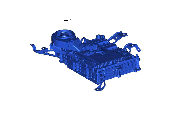
*a Cooling Blower - -
-
-
FUNCTION
-
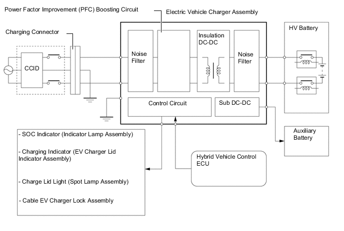
Based on the signal from the hybrid vehicle control ECU, the electric vehicle charger assembly controls the plug-in charge control system. It also controls the charging timer function to set either the charging start time or departure time.
-
The charging connector lock system, EV charger lid lock system, SOC indicator, charging indicator (EV charger lid indicator assembly) and EV charger lid indicator are controlled by the electric vehicle charger assembly.
-
When the power switch is turned off and the charge cable (electric vehicle charger cable assembly) is connected to the charge inlet (electric vehicle charger cable), the electric vehicle charger assembly receives the charger operation permission signal and starts charging.
-
-
OPERATION
-
Alternating current supplied from an external power source is converted into direct current and a booster raises the voltage during charging.
-
Using the sub DC-DC converter, the minimum required power necessary for charging is supplied to the auxiliary battery.
-
During plug-in charging, the electric vehicle charging system is controlled as shown in the illustration.
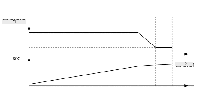
*1 Charging Power *2 Full Charge
-