HYBRID CONTROL SYSTEM
-
FUNCTION OF MAIN COMPONENTS
-
The main components of the plug-in hybrid system have the following functions:
Component Function Hybrid Vehicle Control ECU Performs comprehensive control of the plug-in hybrid system.
-
Information from various sensors as well as from ECUs (ECM, MG ECU, battery ECU assembly and skid control ECU) is received, and based on this the required torque and output power is calculated. The hybrid vehicle control ECU transmits the calculated result to the ECM, MG ECU and skid control ECU.
-
Monitors the SOC of the HV battery.
-
Controls the DC-DC converter.
-
Controls the inverter water pump assembly.
Hybrid Vehicle Transaxle Assembly Motor Generator No. 1 (MG1)
-
MG1, which is driven by the engine, generates high-voltage electricity in order to operate MG2 and charge the HV battery. Also, it functions as a starter to start the engine.
-
Supports MG2 using power supplied from the HV battery to increase driving torque.
Motor Generator No. 2 (MG2)
-
MG2, which is driven by electrical power from MG1 and the HV battery, generates motive force for the drive wheels.
-
During braking, or when the accelerator pedal is not depressed, it generates high-voltage electricity to recharge the HV battery.
Generator Resolver (For MG1) Detects the rotor position, rotational speed and direction of MG1. Motor Resolver (For MG2) Detects the rotor position, rotational speed and direction of MG2. Generator Temperature Sensor (For MG1) Detects the temperature of MG1. Motor Temperature Sensor (For MG2) Detects the temperature of MG2. ATF Temperature Sensor Detects the temperature of ATF. Power Split Planetary Gear Unit Distributes the engine motive force as appropriate to drive the vehicle as well as MG1. Motor Speed Gear Unit Reduces the rotational speed of MG2 in accordance with the characteristics of the planetary gear, in order to increase torque. Inverter with Converter Assembly Inverter Converts the direct current from the boost converter into alternating current for MG1 and MG2, and vice versa (from AC to DC). Boost Converter Boosts the HV battery nominal voltage of DC351.5 V up to a maximum voltage of DC 600 V and vice versa (steps down DC 600 V to DC351.5 V). DC-DC Converter Steps down the HV battery nominal voltage of DC351.5 V to approximately DC 14 V in order to supply electricity to the electrical components, as well as to recharge the auxiliary battery. MG ECU Controls the inverter and boost converter in accordance with the signals received from the hybrid vehicle control ECU, thus operating MG1 and MG2 as either a generator or motor. Temperature Sensor for Inverter with Converter Assembly Detects temperatures in the parts of the inverter with converter assembly as well as the HV coolant temperature. Inverter Current Sensor Detects the current of MG1 and MG2. HV Battery HV Battery (Battery Modules)
-
Supplies electrical power to MG1 and MG2 in accordance with the driving conditions of the vehicle.
-
Recharged by MG1 and MG2 in accordance with the SOC and the driving conditions of the vehicle.
HV Battery Temperature Sensor Detects temperatures in the parts of the HV battery. HV Battery Intake Air Temperature Sensor Detects the Intake air temperature from the battery cooling blower assembly. HV Battery Junction Block Assembly System Main Relays Connects and disconnects the high-voltage circuit between the HV battery and the inverter with converter assembly through the use of signals from the hybrid vehicle control ECU. Battery Current Sensor Detects the input and output current of the HV battery. Battery ECU Assembly
-
Monitors the conditions of the HV battery such as voltage, current and temperature, and transmits this information to the hybrid vehicle control ECU.
-
Monitors the high-voltage system for breakdown of the electrical insulation.
-
Controls the battery cooling blower assembly.
-
Operates the battery heater relay.
Temperature Sensor Detects the temperature of the HV battery, HV battery junction block assembly and HV battery intake air to monitor the condition of the HV battery and hybrid battery junction block assembly and to control the HV battery cooling blower assembly. Battery Heater Heats the HV battery when the temperature of the HV battery is low. Service Plug Grip Shuts off the high-voltage circuit of the HV battery when the service plug grip is removed for vehicle inspection or maintenance. Interlock Switch (for Service Plug Grip/for Inverter Cover) Verifies that the service plug grip and inverter cover are installed. Power Cable (HV Floor Under Wire/Air Conditioner Wire) Connects the HV battery, inverter with converter assembly, hybrid vehicle transaxle assembly and compressor with motor assembly. Inverter Water Pump Assembly Operates under the control of the hybrid vehicle control ECU in order to cool the inverter with converter assembly, MG1 and MG2. Battery Cooling Blower Assembly Operates under the control of the battery ECU assembly in order to cool the HV battery. Auxiliary Battery Supplies electricity to the electrical components. Battery State Sensor Assembly Calculates the current, voltage, temperature, SOC (battery charging percentage), SHC (battery degradation percentage) and SOF (starting performance) of the auxiliary battery. Power Switch Starts and stops the hybrid system. Accelerator Pedal Sensor Assembly Converts the accelerator pedal position into an electrical signal and sends it to the hybrid vehicle control ECU. Shift Lock Control Unit Assembly Shift Lever Position Sensor Converts the shift position into electrical signals and sends them to the hybrid vehicle control ECU. P Position Switch (Transmission Shift Main Switch) Outputs the P position switch signal to the hybrid vehicle control ECU when operated by the driver. Stop Light Switch Detects the depression of the brake pedal. Pattern Select Switch Assembly EV/HV Mode Selection Switch Sends the EV/HV mode selection switch signal to the hybrid vehicle control ECU when operated by the driver. EV AUTO Mode Switch*1 Sends the EV AUTO mode selection switch signal to the hybrid vehicle control ECU when operated the driver. EV CITY Mode Switch*2 Sends the EV CITY mode selection switch signal to the hybrid vehicle control ECU when operated the driver. Drive Mode Switch Sends the power mode, ECO mode or normal mode signal to the hybrid vehicle control ECU when operated by the driver. ECM
-
Performs control of the engine in accordance with the target engine speed and required engine motive force received from the hybrid vehicle control ECU.
-
Transmits various engine operating condition signals to the hybrid vehicle control ECU.
Skid Control ECU (Brake Booster with Master Cylinder Assembly)
-
During braking, it calculates the required regenerative braking force and transmits it to the hybrid vehicle control ECU.
-
Transmits the request to the hybrid vehicle control ECU to limit motive force while the TRC or VSC is operating.
-
Sends a signal to the hybrid vehicle control ECU indicating the current vehicle speed.
Air Conditioning Amplifier Assembly Transmits various A/C state signals to the hybrid vehicle control ECU. Airbag Sensor Assembly During a collision, it transmits the airbag deployment signal to the hybrid vehicle control ECU. Combination Meter Assembly READY Indicator Light Informs the driver that the vehicle is ready to drive. Master Warning Light Illuminates or flashes and the buzzer may sound depending on the message displayed on the multi-information display. Discharge Warning Light Turns on when there is a malfunction in the auxiliary battery charging system. Malfunction Indicator Lamp (MIL) Turns on when there is a malfunction in the hybrid control system or engine control system. Multi-information Display
-
Displays hybrid system indicator.
-
Displays energy monitor.
-
Displays EV drive indicator.
Main Display
-
Displays EV mode indicator.
-
Displays PWR (power) mode indicator.
-
Displays ECO mode indicator.
-
Displays CHG (HV battery charge) mode indicator.
-
Displays EV AUTO mode indicator.*1
-
Displays EV CITY mode indicator.*2
Inverter Battery*1 Supplies power to the power control unit to assist with discharging high voltage components if the output of the auxiliary battery becomes insufficient after the vehicle is involved in a collision. Driving Support ECU*3 Sends a signal to the hybrid vehicle control ECU indicating whether the pre-crash safety system is operating. *1: Destination package for South Korea
*2: Models for Europe
*3: Models with pre-crash safety system
-
-
-
SYSTEM CONTROL
-
Control List
-
The plug-in hybrid system consists of the controls listed below.
Control Outline Hybrid Vehicle Control
-
The hybrid vehicle control ECU calculates the target motive force based on the shift lever position sensor, accelerator pedal opening angle and vehicle speed. It performs control in order to create the target motive force by optimally combining MG1, MG2 and the engine.
-
The hybrid vehicle control ECU calculates the engine motive force based on the target motive force, which has been calculated based on the requirements of the driver and the driving conditions of the vehicle. In order to create this motive force, the hybrid vehicle control ECU transmits the signals to the ECM.
-
The hybrid vehicle control ECU monitors the SOC of the HV battery and the temperature of the HV battery, MG1 and MG2, in order to optimally control these items.
SOC Control
-
The hybrid vehicle control ECU calculates the SOC by estimating the charging and discharging amperage of the HV battery.
-
The hybrid vehicle control ECU constantly performs charge/discharge control based on the calculated SOC in order to maintain the SOC within its target range.
Engine Control The ECM receives the target engine speed and required engine motive force, which were sent from the hybrid vehicle control ECU, and controls the ETCS-i, fuel injection volume, ignition timing, VVT-i and EGR. MG1 and MG2 Main Control
-
MG1, which is driven by the engine, generates high-voltage electricity in order to operate MG2 and charge the HV battery. Also, it functions as a starter to start the engine.
-
MG2, which is driven by electrical power from MG1 and the HV battery, generates motive force for the drive wheels.
-
MG2 generates high-voltage electricity to charge the HV battery during braking (regenerative braking cooperative control), or when the accelerator pedal is not being depressed (energy regeneration).
-
MG1 and MG2 are basically shut down when neutral (N) is selected. In order to stop providing motive force, it is necessary to stop driving MG1 and MG2, because MG1 and MG2 are mechanically joined to the drive wheels.
Inverter Control
-
The inverter converts the direct current from the HV battery into alternating current for MG1 and MG2, or vice versa, in accordance with the signals provided by the hybrid vehicle control ECU via the MG ECU. In addition, the inverter is used to transfer electrical power generated by the MG1 to MG2.
-
The hybrid vehicle control ECU shuts down the inverter if it receives an overheating, overcurrent or voltage fault signal from the inverter via the MG ECU.
Boost Converter Control
-
The boost converter boosts the HV battery nominal voltage of DC351.5 V up to a maximum voltage of DC 600 V, in accordance with the signals provided by the hybrid vehicle control ECU via the MG ECU.
-
The inverter converts the alternating current generated by MG1 or MG2 into the direct current. The boost converter steps down the generated voltage of DC 600 V (maximum voltage) to approximately DC351.5 V, in accordance with the signals provided by the hybrid vehicle control ECU via the MG ECU.
DC-DC Converter Control The DC-DC converter steps down the HV battery nominal voltage of DC351.5 V to approximately DC 14 V in order to supply electricity to the electrical components, as well as to recharge the auxiliary battery. System Main Relay Control To ensure that it is possible to connect and disconnect the high-voltage circuits reliably, the hybrid vehicle control ECU controls the 3 system main relays to connect and disconnect the high-voltage circuits from the HV battery. The hybrid vehicle control ECU also uses the timing of the operation of the 3 system main relays to monitor the operation of the relay contacts. Cooling System Control for Inverter with Converter Assembly In order to cool the inverter with converter assembly, MG1 and MG2, the hybrid vehicle control ECU regulates the inverter water pump assembly according to the signals from the temperature sensor for inverter with converter assembly, temperature sensor for MG1 and temperature sensor for MG2. Cooling System Control for HV Battery In order to maintain the HV battery temperature at the optimum level, the hybrid vehicle control ECU regulates the battery cooling blower assembly according to the signals from the HV battery temperature sensors and HV battery intake air temperature sensor. Regenerative Braking Cooperative Control During braking, the skid control ECU calculates the required regenerative braking force and transmits it to the hybrid vehicle control ECU. Upon receiving this signal, the hybrid vehicle control ECU transmits the actual regenerative braking control value to the skid control ECU. Based on this result, the skid control ECU calculates and executes the required hydraulic braking force. TRC/VSC Cooperative Control The skid control ECU transmits the request to the hybrid vehicle control ECU to limit motive force while the TRC or VSC is operating. The hybrid vehicle control ECU controls the engine and MG2 in accordance with the present driving conditions in order to suppress the motive force. For details, refer to Brake Control System. During Collision Control During a collision, if the hybrid vehicle control ECU receives the airbag deployment signal from the airbag sensor assembly, it turns the system main relays off in order to shut off the high-voltage from the HV battery. Cruise Control System Operation Control*1 When the hybrid vehicle control ECU receives the cruise control switch signal, it controls the motive forces of the engine and MG2 to be an optimum combination in order to obtain the target vehicle speed by the driver's demand. For details, refer to Cruise Control System. Dynamic Radar Cruise Control System Operation Control*2 Upon receiving a motive force request signal from the driving support ECU assembly, the hybrid vehicle control ECU optimizes the motive forces of the engine, MG2 in order to obtain the target vehicle speed. For details, refer to Dynamic Radar Cruise Control System. Shift Control The hybrid vehicle control ECU detects the driver's desired shift state (P, R, N, D or B) in accordance with the signals provided by the shift lever position sensor and P position switch. Based on these inputs and vehicle operating conditions, the hybrid vehicle control ECU controls MG1, MG2 and the engine to match the selected shift state. EV Mode Control
-
Uses power from the HV battery to drive mainly MG2.
-
Depending on the driving conditions and accelerator pedal opening angle, either MG1 or the engine will be operated to increase driving torque.
HV Battery Charge Mode Control When the vehicle is driven in HV mode or EV mode, HV battery charge mode control charges the HV battery. EV AUTO Mode Control*3 Depending on the driving status and accelerator pedal opening angle, EV AUTO mode controls the engine to ensure smooth starting. EV CITY Mode Control*4 EV CITY mode limits motor output and minimizes the operation of the gasoline engine. Power Mode Control When the power mode switch (combination switch assembly) is operated by the driver, the hybrid vehicle control ECU modulates the response of the accelerator pedal operation to optimize acceleration. ECO Mode Control When the ECO mode switch (combination switch assembly) is operated by the driver, the hybrid vehicle control ECU modulates the response of the accelerator pedal operation to support Eco driving. ECO Driving Based on Prediction Control By gathering past driving records in the navigation receiver assembly database, ECO driving based on prediction control will assist to decelerate the vehicle at each memorized stopping or deceleration position. Brake Override System The driving torque is restricted when both the accelerator and brake pedals are depressed. (For the Activation Conditions and Inspection Method, refer to the Repair Manual) Engine Immobiliser Prohibits fuel delivery, ignition and starting the hybrid control system if an attempt is made to start the hybrid control system with an invalid key. Drive Start Control System If an inappropriate accelerator pedal or shift operation is performed, vehicle speed and acceleration are restricted. *1: Models with cruise control system
*2: Models with dynamic radar cruise control system
*3: Destination package for South Korea
*4: Models for Europe
-
-
-
Plug-in Hybrid System Activation (READY-on State)
-
The plug-in hybrid system is activated by pressing the power switch while the brake pedal is being depressed. At this time, the READY indicator light flashes until the system check is completed. When the READY indicator light turns on, the plug-in hybrid system has started and the vehicle is ready to drive.
-
Even if the driver turns the power switch on (READY), sometimes the hybrid vehicle control ECU will not start the engine. The engine will only start if conditions such as engine coolant temperature, SOC, HV battery temperature and electrical load require an engine start.
-
After driving, when the driver stops the vehicle and turns the P position switch on, the hybrid vehicle control ECU allows the engine to continue running. The engine will stop after the SOC, HV battery temperature and electrical load reach a specified level.
Note
When the plug-in hybrid system is unavoidably required to be stopped while driving, the system can be forced to stop by pressing and holding the power switch for approximately 2 seconds or more or pushing the power switch 3 times or more in a row. At this time, the power source will change to on (ACC).
-
-
EV Mode (Except Destination Package for South Korea)
-
Even if there is a sufficient amount of electricity remaining in the HV battery and EV driving range is being displayed on the multi-information display etc., EV driving (driving using only the electric motor) may be canceled and both gasoline engine and electric motor are used depending on the situation (EV driving will be returned to automatically after EV driving becomes possible again).
-
When vehicle speed is more than approximately 135 km/h (84 mph).
-
When power is needed temporarily, for example when the accelerator pedal is depressed firmly or when accelerating suddenly.
-
When the temperature of the hybrid system is high.
The vehicle has been left in the sun, driven on a hill, driven at high speeds, etc.
-
When the temperature of the hybrid system is low.
-
When the heater is switched on when the outside temperature is below about -10°C (14°F).
-
When the rear windowshield defogger switch is pressed.
-
When the system determines that the gasoline engine needs to be started.
EV driving may be canceled automatically in the following circumstances:
-
-
While driving, the vehicle switches between EV mode and HV mode in accordance with the SOC of the HV battery. Switching from EV mode to HV mode is automatically performed according to the SOC of the battery.
-
While driving in EV mode, the mode can be manually changed to HV mode using the EV/HV mode selection switch (integration control and panel sub-assembly). The driver can preserve the SOC of the HV battery by selecting HV mode in situations such as when driving at high speeds, which quickly drains the battery. This enables the driver to control the battery usage by themselves.
-
-
EV Mode/EV AUTO Mode (Destination Package for South Korea)
-
Even if there is a sufficient amount of electricity remaining in the HV battery and EV driving range is being displayed on the multi-information display etc., EV driving (driving using only the electric motor) may be canceled and both gasoline engine and electric motor are used depending on the situation (EV driving will be returned to automatically after EV driving becomes possible again).
-
When vehicle speed is more than approximately 84 mph (135 km/h).
-
When power is needed temporarily, for example when the accelerator pedal is depressed firmly or when accelerating suddenly. (EV auto mode only)
-
When the temperature of the hybrid system is high.
The vehicle has been left in the sun, driven on a hill, driven at high speeds, etc.
-
When the temperature of the hybrid system is low.
-
When the heater is switched on when the outside temperature is below about-10°C (14°F).
-
When the windowshield defogger switch is pressed.
-
When the system determines that the gasoline engine needs to be started.
EV driving may be canceled automatically in the following circumstances:
Tech Tips
The gasoline engine may also operate in circumstances other than those listed above, depending on conditions.
-
-
While driving, the vehicle switches between EV mode/EV AUTO mode and HV mode in accordance with the SOC of the HV battery. Switching from EV mode to HV mode/EV AUTO mode is automatically performed according to the SOC of the battery.
-
While driving in EV mode/EV AUTO mode, the mode can be manually changed to HV mode using the EV/HV mode selection switch (integration control and panel sub-assembly). The driver can preserve the SOC of the HV battery by selecting HV mode in situations such as when driving at high speeds, which quickly drains the battery. This enables the driver to control the battery usage by themselves.
-
-
Power Mode and ECO Mode
-
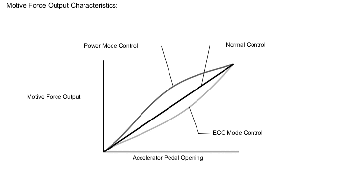
During power mode, the hybrid vehicle control ECU optimizes acceleration feel by increasing the power output more quickly at the beginning of accelerator pedal operation.
-
During ECO mode, the hybrid vehicle control ECU optimizes fuel economy and driving performance by gently generating the motive force in comparison to accelerator pedal operation. At the same time, it supports Eco driving by optimizing the air conditioning performance.
-
-
EV CITY Mode (Models for Europe)
-
EV CITY mode limits motor output and minimizes the operation of the gasoline engine.
-
If the kick down switch is turned on while in EV CITY mode, the engine starts.
-
-
HV Battery Charge Mode
-
The drive mode can be changed to HV battery charge mode by pressing and holding the EV/HV mode switch.
-
While the vehicle is driven in HV mode, HV battery charge mode control charges the HV battery more than normal using the engine.
-
As the engine is used to charge the HV battery, battery charge mode consumes more fuel than normal HV mode.
-
-
Hybrid Vehicle Control
-
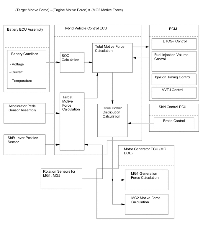
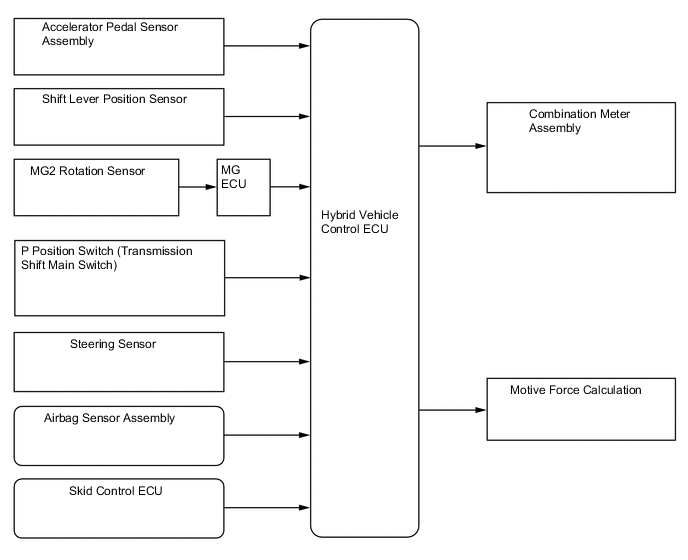
The hybrid vehicle control ECU detects the degree to which the accelerator pedal is depressed using the signals from the accelerator pedal sensor assembly and detects the shift position signals from the shift lever position sensor. The hybrid vehicle control ECU receives the speed signals from the MG1 and MG2 resolvers via the MG ECU. The hybrid vehicle control ECU determines the driving conditions of the vehicle in accordance with this information, and optimally controls the motive forces of MG1, MG2 and the engine. Furthermore, the hybrid vehicle control ECU optimally controls the output and torque of MG1, MG2 and the engine in order to deliver lower fuel consumption and cleaner exhaust emissions.
-
The hybrid vehicle control ECU calculates the engine motive force based on the calculated target motive force, and by taking the SOC and the temperature of the HV battery into consideration. The value obtained by subtracting the engine motive force from the target motive force is the MG2 motive force.
-
The ECM performs control of the engine in accordance with the target engine speed and required engine motive force received from the hybrid vehicle control ECU. Furthermore, the hybrid vehicle control ECU appropriately operates MG1 and MG2 in order to provide the required MG1 generation force and the required MG2 motive force.
Figure 1. Flow of Motive Force Calculation
-
-
SOC Control
-
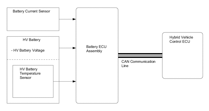
The hybrid vehicle control ECU calculates the SOC of the HV battery based on the charge/discharge amperage detected by the battery current sensor. The hybrid vehicle control ECU constantly performs charge/discharge control based on the calculated SOC in order to maintain the SOC within its target range.
-
While the vehicle is in motion, the HV battery undergoes repetitive charge/discharge cycles, as it becomes discharged by MG2 during acceleration and charged by regenerative braking during deceleration.
-
When the SOC is below the lower level, the hybrid vehicle control ECU increases the power output of the engine to operate MG1, which charges the HV battery.
-
The battery ECU assembly converts the HV battery related signals (voltage, current and temperature) into digital signals, and transmits them to the hybrid vehicle control ECU via serial communication. These signals are needed to determine the SOC that is calculated by the hybrid vehicle control ECU.
-
-
Engine Control
-
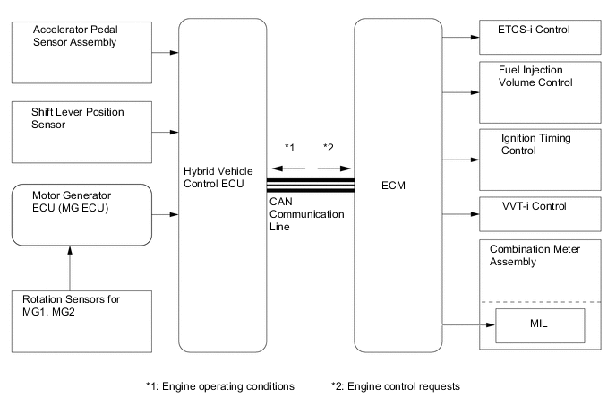
The ECM receives the target engine speed and required engine motive force, which were sent from the hybrid vehicle control ECU, and controls the ETCS-i, fuel injection volume, ignition timing, VVT-i and EGR.
-
The ECM transmits the operating conditions of the engine to the hybrid vehicle control ECU.
-
Upon receiving the engine stop signal from the hybrid vehicle control ECU in accordance with the basic hybrid vehicle control, the ECM will stop the engine.
-
-
MG1 and MG2 Main Control
-
MG1, which is driven by the engine, generates high-voltage electricity in order to operate MG2 and charge the HV battery. Also, it functions as a starter to start the engine.
-
MG2, which is driven by electrical power from MG1 and the HV battery, generates motive force for the drive wheels.
-
MG2 generates high-voltage electricity to charge the HV battery during braking (regenerative braking cooperative control), or when the accelerator pedal is not being depressed (energy regeneration).
-
MG1 and MG2 are basically shut down when neutral (N) is selected. In order to stop providing motive force, it is necessary to stop driving MG1 and MG2, because MG1 and MG2 are mechanically joined to the drive wheels.
-
The MG ECU controls the Insulated Gate Bipolar Transistors (IGBTs) in the Intelligent Power Module (IPM) based on the signals received from the hybrid vehicle control ECU. The IGBTs are used for switching for the U, V, and W phases of each motor generator. There are 6 IGBTs that switch on and off to control each individual motor generator in accordance with operation as either a motor or as a generator.
-
The illustration below describes the basic control used when the motor generator functions as a motor. The IGBTs in the IPM switch on and off to supply 3-phase alternating current to the motor generator. In order to create the motive force required of the motor generator as calculated by the hybrid vehicle control ECU, the MG ECU switches the IGBTs on and off in order to control the speed of the motor generator.
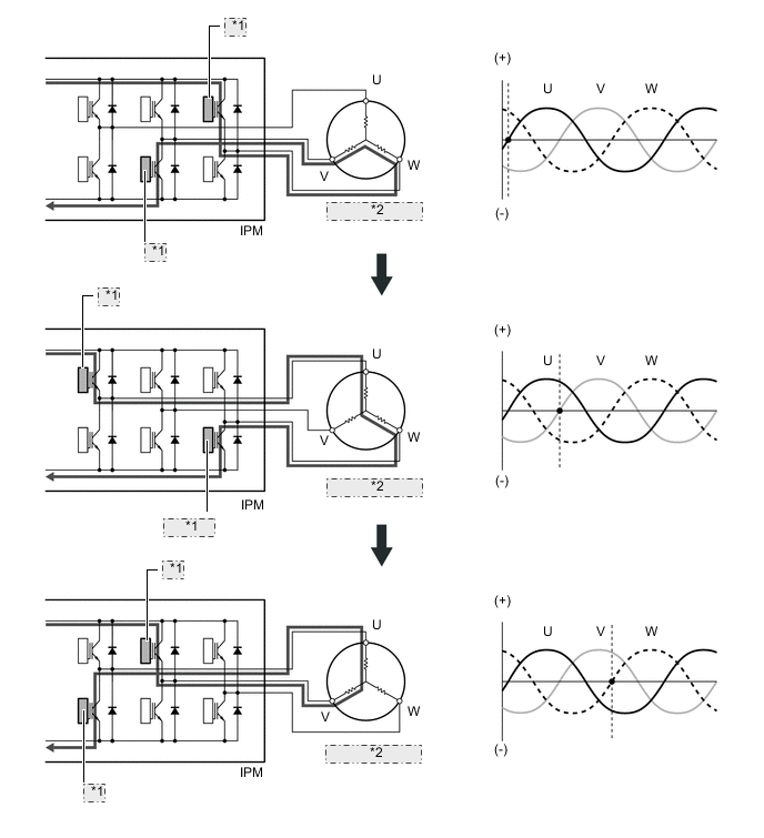
*1 IGBT: ON *2 Motor Generator -
The illustration below describes the basic control used when the motor generator functions as a generator. The current that is generated sequentially by the 3-phases of the motor generator, which is driven by the wheels, is utilized to charge the HV battery or drive another motor generator.
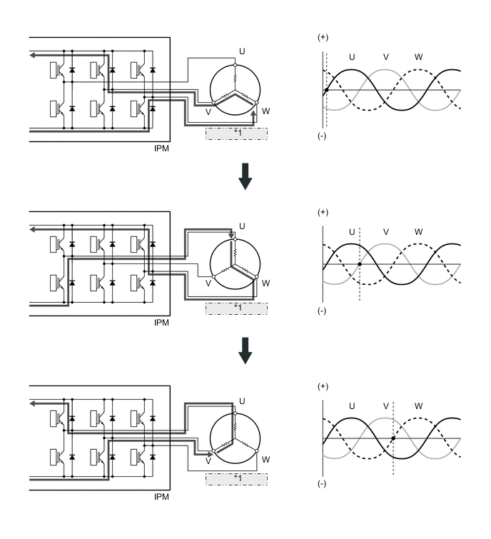
*1 Motor Generator
-
-
Inverter Control
-
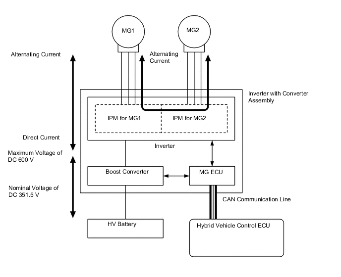
The inverter converts the direct current from the HV battery into alternating current for MG1 and MG2, or vice versa. In addition, the inverter takes power generated by MG1 and supplies it to MG2. However, the electricity generated by MG1 is converted into direct current inside the inverter before being converted back into the alternating current by the inverter for use by MG2. This is necessary because the frequency of the alternating current output by MG1 is not appropriate for control of MG2.
-
The MG ECU controls the IPMs for switching the three-phase alternating current of MG1 and MG2 in accordance with the signals received from the hybrid vehicle control ECU.
-
When the hybrid vehicle control ECU has received an overheating, overcurrent, or voltage fault signal from the MG ECU, the hybrid vehicle control ECU transmits a shut down control signal to the MG ECU, in order to turn off the IPMs.
-
-
Boost Converter Control
-
The boost converter boosts the HV battery nominal voltage of DC351.5 V up to a maximum voltage of DC 600 V, in accordance with the signals provided by the hybrid vehicle control ECU via the MG ECU.
-
The inverter converts the alternating current generated by MG1 or MG2 into direct current. The boost converter steps down the generated voltage of DC 600 V (maximum voltage) to approximately DC351.5 V, in accordance with the signals provided by the hybrid vehicle control ECU via the MG ECU.
-
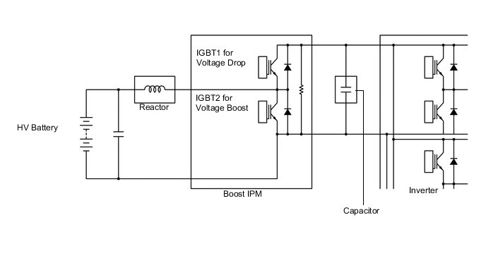
The boost converter consists of the boost IPM with built-in IGBTs that perform switching control, the reactor that stores the electrical power and generates the electromotive force, and the capacitor that charges and discharges the boosted high-voltage electricity.
-
The flow of the boost converter boosting is as described below.
Step Outline 1 IGBT2 turns on, causing the voltage of the HV battery (nominal voltage of DC351.5 V) to charge the reactor. As a result, the reactor stores the electrical power. 2 IGBT2 turns off, causing the reactor to produce an electromotive force (the current continues to flow from the reactor). This electromotive force causes the voltage to rise to a maximum voltage of DC 600 V. Induced by the electromotive force that is created by the reactor, the current that is flowing from the reactor flows into the inverter and the capacitor at the boosted voltage. 3 IGBT2 turns on again to cause the voltage of the HV battery to charge the reactor. While this happens, by discharging the electrical power (maximum voltage of DC 600 V) stored in the capacitor, electrical power continues to be supplied to the inverter. 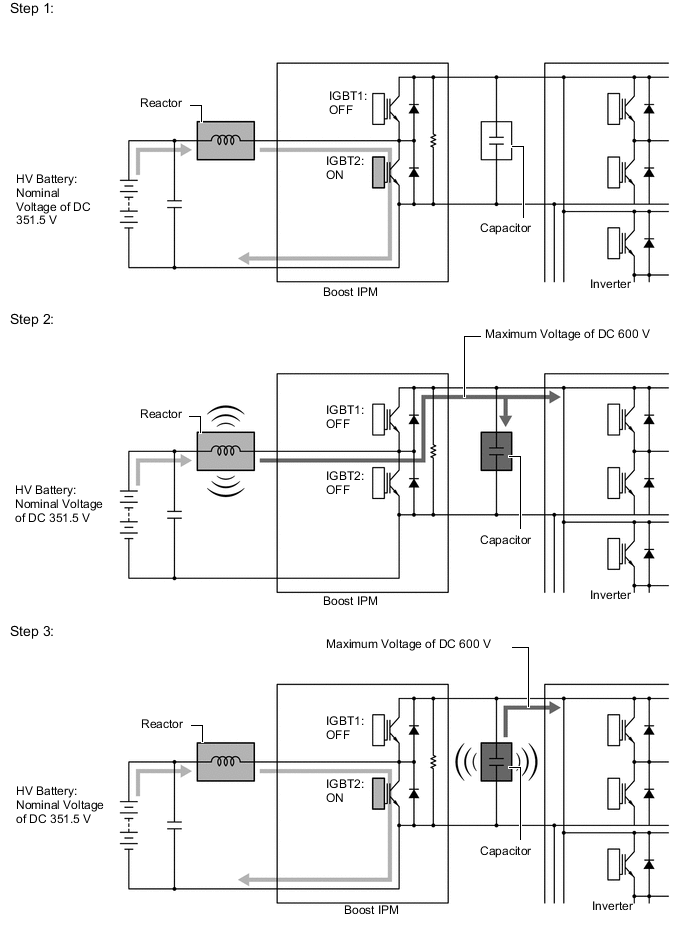
-
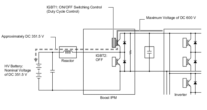
The alternating current which is generated by MG1 or MG2 for the purpose of charging the HV battery is converted into direct current (maximum voltage of DC 600 V) by the inverter. Then, the boost converter is used to step down the voltage to approximately DC351.5 V. This is accomplished by IGBT1 being switched on and off using duty cycle control, intermittently interrupting the electrical power provided to the reactor by the inverter.
-
-
DC-DC Converter Control
-
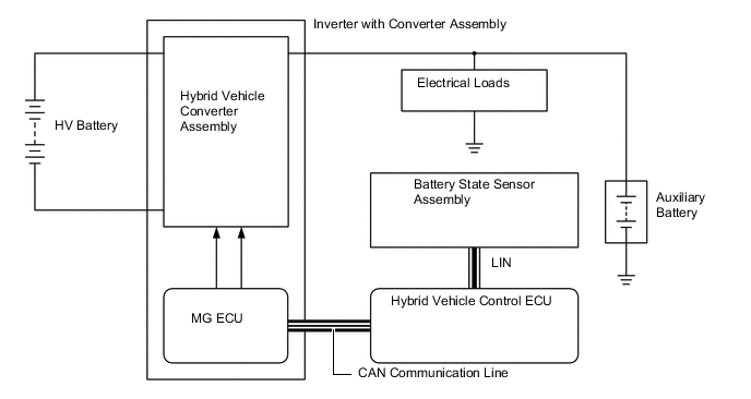
The DC-DC converter steps down the HV battery nominal voltage of DC351.5 V to approximately DC 14 V in order to supply electricity to the electrical components, as well as to recharge the auxiliary battery.
-
In order to regulate the output voltage from the DC-DC converter, the hybrid vehicle control ECU transmits an output voltage request signal to the DC-DC converter in response to auxiliary battery temperature sensor signals.
-
-
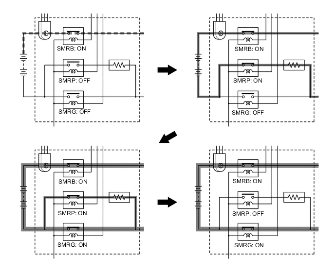
System Main Relay Control
-
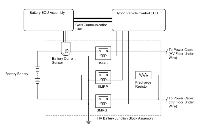
The plug-in hybrid vehicle control ECU controls the system main relays to connect and disconnect the high-voltage circuit from the HV battery. The hybrid vehicle control ECU also uses the timing of the operation of the system main relays to monitor the operation of the relay contacts.
-
A total of 3 relays, 1 for the positive side (SMRB), and 2 for the negative side (SMRP, SMRG), are provided to ensure proper operation.
-
When the plug-in hybrid system changes to the READY-on state, the hybrid vehicle control ECU turns on SMRB and SMRP in sequence, and applies the current through the precharge resistor. After that, it turns SMRG on, and applies the current by bypassing the precharge resistor. Then it turns SMRP off. As the controlled current is initially allowed to pass through the precharge resistor in this manner, the contact point in the circuit is protected from damage that could be caused by an inrush current.
-
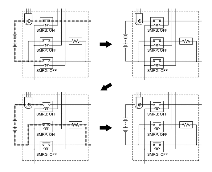
When the plug-in hybrid system changes to a state other than the READY-on state, the hybrid vehicle control ECU turns SMRG off first. Next, it turns SMRB off after determining whether or not SMRG is operating properly. After that, it turns on SMRP and then off after determining whether or not SMRB is operating properly. As a result, the hybrid vehicle control ECU verifies that the respective relays have been properly turned off.
-
-
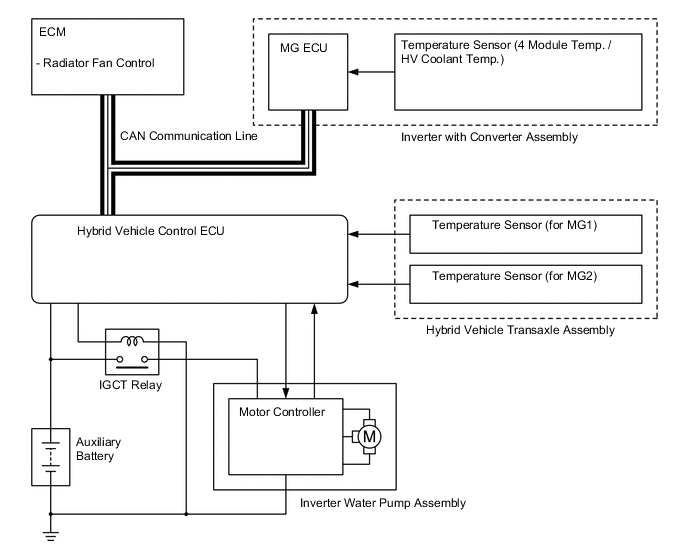
Cooling System Control for Inverter with Converter Assembly
-
The hybrid vehicle control ECU receives signals from the temperature sensors for the inverter with converter assembly, temperature sensor for MG1 and temperature sensor for MG2. Then, the hybrid vehicle control ECU actuates the inverter water pump assembly over 3 levels using duty cycle control, in order to cool the inverter with converter assembly, MG1 and MG2.
-
When the HV coolant temperature rises above a certain level, the hybrid vehicle control ECU transmits a radiator fan drive request signal to the ECM. In response to that signal, the ECM actuates the radiator fan to restrain the HV coolant temperature increase, ensuring the cooling of the inverter with converter assembly, MG1 and MG2.
-
The MG ECU converts the temperature sensor signals into digital signals, and transmits them to the hybrid vehicle control ECU via serial communication.
-
-
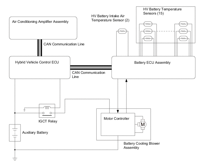
Cooling System Control for HV Battery
-
The hybrid vehicle control ECU receives signals from the HV battery temperature sensors and HV battery intake air temperature sensor. Then, the hybrid vehicle control ECU steplessly actuates the battery cooling blower assembly using duty cycle control, in order to maintain the HV battery temperature within the specified range.
-
The battery ECU assembly converts the HV battery related signals (voltage, current and temperature) into digital signals, and transmits them to the hybrid vehicle control ECU via serial communication. Also, the battery ECU assembly detects and transmits the blower speed feedback frequency, which is necessary to perform the cooling system control, to the hybrid vehicle control ECU.
-
-
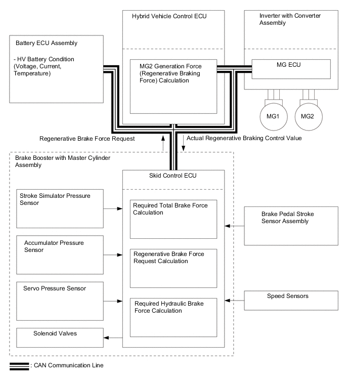
Regenerative Braking Cooperative Control
-
The skid control ECU calculates the total braking force needed based on the brake regulator pressure and brake pedal stroke when the driver depresses the brake pedal.
-
After calculating the required total braking force, the skid control ECU sends a regenerative braking force request to the hybrid vehicle control ECU. The hybrid vehicle control ECU replies with the amount of actual regenerative braking (regenerative braking control value).
-
The hybrid vehicle control ECU uses MG2 to create the negative torque (deceleration force), thus carrying out regenerative braking.
-
The skid control ECU controls the brake actuator solenoid valves and generates wheel cylinder pressure. The pressure that is generated is what remains after the actual regenerative braking control value has been subtracted from the required total braking force.
-
-
Drive Start Control System
-
When abnormal driver accelerator pedal and shift operations are detected, the system limits the motive force and informs the driver.
CAUTION:
When the system is operating, even if the driver depresses and holds the accelerator pedal, motive force may increase on an uphill slope and decrease on a downhill slope. This behavior allows the system to restrict the vehicle speed and acceleration below the predetermined limit on slopes and is not a malfunction.
-
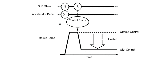
Control during Reverse Operation
-
Responds to excessive depression of the accelerator pedal while operating in reverse.
-
Corrects motive force according to the road grade and steering angle.
Control Start Conditions (When all of the following conditions are met, control starts.)
-
Shift state is R.
-
Accelerator pedal is depressed.
Control Operation Limits the motive force so the vehicle speed and acceleration are at or below a certain level. Control Stop Conditions
-
Shift state is not R.
-
Accelerator pedal is fully released.
-
-
-
Control during Manual Shift Operation
-
Responds to shift operations with the accelerator pedal depressed.
-
Changes the limit amount according to the manual shift operation pattern.
-
Corrects motive force according to the road grade and steering angle.
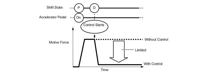
Control when Starting Off from a Parked Position Control Start Conditions (When all of the following conditions are met, control starts.)*
-
Shift state is changed from P to D, or P to R.
-
Accelerator opening angle is approximately 1/5 or higher.
Control Operation Limits the motive force so the vehicle speed and acceleration are at or below a certain level. Control Stop Conditions
-
Shift state is P or N.
-
Accelerator pedal is fully released.
Tech Tips
*: When attempting to select a shift state other than park (P) with park (P) selected and the accelerator pedal depressed, because the shift state will not change from park (P), drive-start control will not operate.
Figure 2. Image of Control when Starting Off from a Parked Position
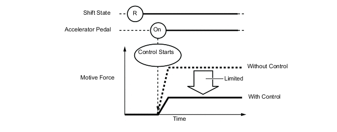
Control during Other Situations Control Start Conditions (When all of the following conditions are met, control starts.)
-
Shift state is changed from R to D, D to R, B to R or N to R.
-
Accelerator opening angle is approximately 1/5 or higher.
Control Operation Limits the motive force so the vehicle speed and acceleration are at or below a certain level. Control Stop Conditions
-
Shift state is P or N.
-
Accelerator pedal is fully released.
Figure 3. Image of Control during Other Situations
CAUTION:
-
The motive force restraint level differs in the above 2 situations.
-
During control while a manual shift state is performed (from control start until the accelerator pedal is released), the system informs the driver of the control via the multi-information display.
-
-
-
-
-
FUNCTION
-
Drive Mode Select
-
By pressing the drive mode switch (pattern select switch), the drive mode can be changed to "ECO", "Normal" or "Power" accordingly.
-
If the power switch is turned off , the latest mode will maintained when the power switch is turned to ON.*1
-
If the power switch is turned off with "Normal" or "ECO" mode selected, the latest mode will maintained when the power switch is turned to ON. However, if "Power" mode is selected when the power switch is turned off, the drive mode will change to "Normal" mode when the power switch is turned to ON.*2
Tech Tips
-
*1: Destination package for South Korea
-
*2: Except destination package for South Korea
-
-
-
-
DIAGNOSIS
-
When the hybrid vehicle control ECU detects a malfunction in the plug-in hybrid system, the hybrid vehicle control ECU performs diagnosis and memorizes information related to the fault. To inform the driver of the malfunction, the hybrid vehicle control ECU illuminates or blinks the Malfunction Indicator Lamp (MIL). At the same time, a Diagnostic Trouble Code (DTC) is stored in memory.
-
3-digit information codes (INF codes) are provided with a conventional DTC as a subset of the primary 5-digit code. This enables the troubleshooting procedure to further narrow down the possible trouble areas to identify the problem.
-
DTCs can be read by connecting the GTS (Global TechStream) to the DLC3. For details, refer to the Repair Manual.
-