HYBRID CONTROL SYSTEM
-
OUTLINE
-
A THS-II Plug-in (TOYOTA Hybrid System-II Plug-in) is used. By incorporating a plug-in charge control system into the THS-II (TOYOTA Hybrid System-II) Hybrid synergy drive concept, an external power source can be used to charge the lithium ion HV battery (plug-in charging).
-
A dual motor drive system has been adopted. By incorporating an additional one-way clutch in the HV transaxle, the operating torque of MG1 (Motor Generator No. 1) can be transmitted to the wheels. This allows the vehicle to be driven in EV drive mode at even during rapid acceleration.
-
By optimally controlling the ratio of drive torque provided by the engine and motors (MG1 and MG2) and the electrical generation of MG1 and MG2, the hybrid vehicle control ECU can maintain a high state of charge of the HV battery, providing for excellent vehicle performance and fuel economy.
-
A solar charging system has been adopted. By using solar panels installed in the roof of the vehicle, electricity is generated and used to charge the HV battery and auxiliary battery. By allowing the HV battery to be charged while the vehicle is parked and suppressing the consumption of the HV battery while the vehicle is being driven, the distance the vehicle can be driven in EV drive mode is increased and fuel economy is improved.*
*: Models with solar charging system
-
By using a high capacity lithium ion HV battery with improved output, dual-motor drive system, battery heating system and heat pump air-conditioning system, increased EV drive mode range and performance have been realized.
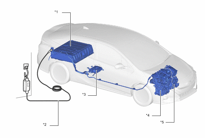
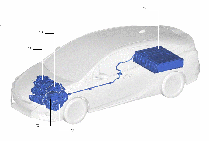
*1 HV Battery *2 Charge Cable (Electric Vehicle Charger Cable Assembly) *3 Electric Vehicle Charger Assembly *4 Engine *5 Hybrid Vehicle Transaxle Assembly - -
-
-
SPECIFICATION
-
Motor Generator
Item Specification MG1 MG2 Type Permanent Magnet Motor Permanent Magnet Motor Function Generate, Engine Starter Generate, Drive Wheels Maximum System Voltage V DC 600 DC 600 Maximum Output kW (HP) 23 (31) 53 (71) Maximum Torque N*m (ft.*lbf) 40 (30) 163 (120) Cooling System Water-cooled Water-cooled -
Inverter with Converter Assembly
Item Specification Boost Converter Rated Voltage (Inverter Side) V DC 600 Rated Voltage (HV Battery Side) V DC 351.5 DC-DC Converter Rated Output Voltage V DC 11.0 to 15.0 Maximum Output Current A 100 -
Cooling System (for Inverter with Converter Assembly and Hybrid Vehicle Transaxle Assembly)
Item Specification Inverter Water Pump Assembly Motor Type Brushless Discharge Volume Liter (US qts, Imp. qts) 10 (10.6, 8.8)/min. or greater Coolant Type Toyota Genuine Super Long Life Coolant (SLLC) Color Pink Capacity Liter (US qts, Imp. qts) 1.4 (1.5, 1.21) Maintenance Intervals First Time km (miles) 240000 (150000) Subsequent km (miles) Every 80000 (50000)
-
-
MAIN FEATURES
-
The THS-II Plug-in control has the following features.
Item Outline Idle Stop Idling of the engine is automatically stopped (idle stop) to reduce energy loss. HV Mode This allows the vehicle to be driven using only the electric motor when engine efficiency is low. Additionally, electricity is generated when engine efficiency is high. Control is performed to maximize the total efficiency of the vehicle. EV Mode By charging and accumulating electric power into the larger capacity HV battery from an external power source, the vehicle can be driven at a maximum of approximately 135 km/h (84 mph) using only the electric motor. Motor Assist The electric motor supplements the engine power when accelerating. Regenerative Braking
(Energy Regeneration)
During deceleration and while depressing the brake pedal, part of the energy that normally would be lost as heat is collected as electrical energy to be reused, such as for motor power. -
The mechanism of the THS-II Plug-in is as follows.
-
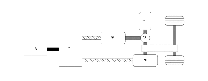
The THS-II Plug-in consists of mainly the engine, hybrid vehicle transaxle assembly, inverter with converter assembly and HV battery, and employs a series/parallel-type hybrid system.
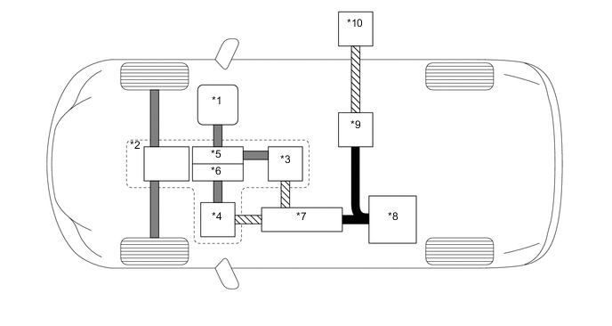
*1 Engine *2 Hybrid Vehicle Transaxle Assembly *3 Motor Generator No. 1 (MG1) *4 Motor Generator No. 2 (MG2) *5 Power Split Planetary Gear Unit (Compound Gear Unit) *6 Motor Speed Reduction Gear Unit (Compound Gear Unit) *7 Inverter with Converter Assembly *8 HV Battery *9 Electric Vehicle Charger Assembly *10 Charge Cable (Electric Vehicle Charger Cable Assembly) 
Electrical Power Path (DC) 
Electrical Power Path (AC) 
Mechanical Power Path - - Tech Tips
Generally, there are 3 types of hybrid systems: series-type hybrid system, parallel-type hybrid system and series/parallel-type hybrid system.
-
In a series-type hybrid system, the motor rotates the wheels, and the engine, using a generator, acts as an electric power source for the motor.
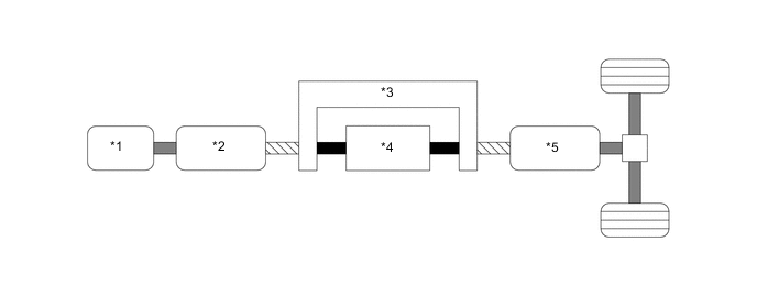
*1 Engine *2 Generator *3 Inverter *4 HV Battery *5 Motor - - Electrical Power Path (DC) Electrical Power Path (AC) Mechanical Power Path - - -
In a parallel-type hybrid system, both the engine and the motor generator directly rotate the wheels. In addition to supplementing the power of the engine, the motor generator can also serve as a generator to charge the HV battery while the vehicle is in motion. Driving the vehicle only with the motor generator is also possible.
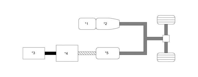
*1 Engine *2 Transmission *3 HV Battery *4 Inverter *5 Motor Generator - - Electrical Power Path (DC) Electrical Power Path (AC) Mechanical Power Path - - -
In a series/parallel-type hybrid system, aspects of both a series-type hybrid system and a parallel-type hybrid system are combined. The system has 2 motor generators. Electricity can be generated by motor generator No. 1 using engine power. The generated electricity is used to charge the HV battery and also to power motor generator No. 2.
*1 Engine *2 Power Split Planetary Gear Unit *3 HV Battery *4 Inverter *5 Motor Generator No. 1 *6 Motor Generator No. 2 Electrical Power Path (DC) Electrical Power Path (AC) Mechanical Power Path - -
-
-
This system optimally performs cooperative control of the engine, and Motor Generator No. 1 (MG1) and Motor Generator No. 2 (MG2) in the hybrid vehicle transaxle assembly that provides excellent transmission performance.
-
The system has 2 batteries, which are used for different purposes. One is the HV battery (nominal voltage of DC 351.5 V) which stores electrical power to drive the vehicle, and the other is the auxiliary battery (nominal voltage of DC 12 V) which supplies electrical power to the electrical components.
-
Furthermore, this system uses a variable-voltage system consisting of the high-output HV battery (nominal voltage of DC 351.5 V), a boost converter that boosts the operating voltage of MG1 and MG2 to a maximum voltage of DC 600 V, and an inverter which converts direct current and alternating current.
-
Since hybrid vehicles are not equipped with a conventional alternator, the high-voltage from the HV battery is stepped down to approximately DC 14 V using a DC-DC converter in order to charge the auxiliary battery. Also, the HV battery regularly charges and discharges within the constant State of Charge (SOC) range while the vehicle is running, thus, recharging from external power sources is not necessary.
*1 Engine *2 Hybrid Vehicle Transaxle Assembly
- Motor Generator No. 1 (MG1)
- Motor Generator No. 2 (MG2)
*3 Inverter with Converter Assembly
- Inverter
- Boost Converter
- DC-DC Converter
*4 HV Battery *5 Auxiliary Battery - - -
A cooling system that is independent from the engine cooling system is provided to cool the inverter with converter assembly and ATF.
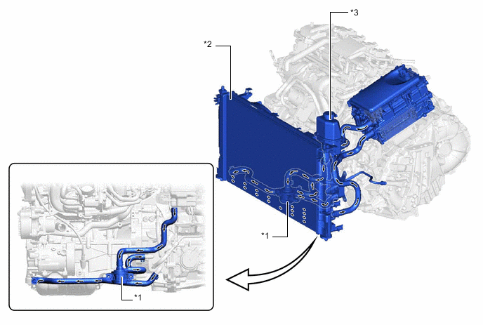
*1 Inverter Water Pump Assembly *2 Radiator Assembly *3 Inverter Reserve Tank - - 
HV Coolant Flow - -
-
-
-
PRECAUTION
-
Hybrid Vehicle High-voltage Safety Measures
-
High-voltage safety is comprised of 2 points: "Insulation of High-voltage Circuits" and "Cut-off of High-voltage Circuits". The plug-in hybrid system also detects whether or not a decrease in insulation resistance has occurred between the high-voltage system and body ground.
-
-
Insulation of High-voltage Circuits
-
High-voltage circuits are used between the HV battery, inverter with converter assembly, hybrid vehicle transaxle assembly and compressor with motor assembly. Each of these items is connected by the power cable (HV floor under wire) and is electrically insulated using cases and covers.
-
The power cable are also shielded using a mesh conductor built into the electrical insulation of the wires. The shielding is grounded to the chassis of the vehicle and its main purpose is to prevent electromagnetic interference.
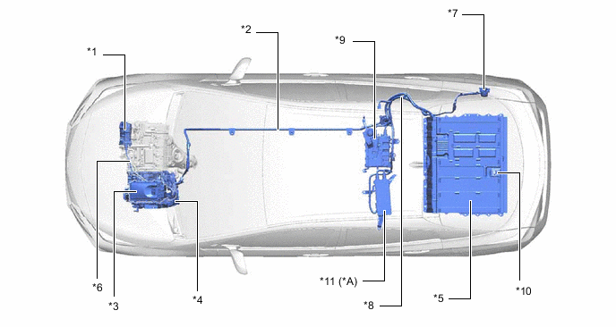
*A Models with Solar Charging System - - *1 Compressor with Motor Assembly *2 Power Cable (HV Floor Under Wire) *3 Inverter with Converter Assembly *4 Hybrid Vehicle Transaxle Assembly *5 HV Battery *6 Power Cable (Air Conditioner Wire) *7 Charge Inlet (AC Charger Inlet Cable) *8 Power Cable (HV Battery Charger Wire) *9 Electric Vehicle Charger Assembly *10 Service Plug Grip *11 Solar Energy Control ECU - -
-
-
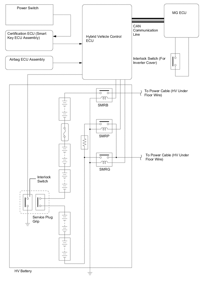
Cut-off of High-voltage Circuits
-
When any of the conditions below occur, the System Main Relays (SMRs) are automatically shut off by the hybrid vehicle control ECU.
-
The power switch is turned off.
-
Any airbag is deployed.
-
Inverter cover is removed (interlock circuit is opened).
-
Service plug grip handle is unlocked (interlock circuit is opened).
-
A specified malfunction occurs.
-
-
-